I/O connection
● Create a low-impedance ground connection for additional cabinets, system components,
and distributed devices with the largest possible cross-section (at least 16 mm²).
● Ground unused lines at one end in the cabinet.
● Choose the greatest possible clearance between the power and signal cables (at least 20
cm). The greater the distance over which the cables are routed in parallel, the greater the
clearance must be. You must install additional shields if sufficient clearance cannot be
maintained.
● Avoid unnecessarily long cable loops.
● Surge suppressors – e.g. RC elements or varistors – must be connected to the solenoids of
contactors and relays in the device.
● In order to reduce noise/interference entering or exiting via the cable, filter auxiliary voltages
in the control cabinet.
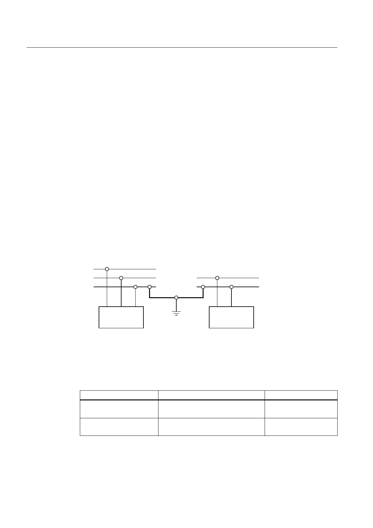
6.3 Potential concept
A noise-free connection between the internal and external supply voltage can be achieved by
connecting the 0 V potentials to each other and grounding them. This also eliminates the need
for the control circuit insulation monitor required by DIN EN 60204-1.
,QWHUQDO
ORDGV
([WHUQDO
ORDGV
3
0
3
0
1
Figure 6-3 Potential concept
6.4 Cable cross-sections
Table 6-1 Cable cross-sections
Object Cross-section Remark
Power cable Max. 240 mm
2
500 kcmil (MCM)
max. 4 per terminal
Cabinet protective conductor Max. 120 mm²
250 kcmil (MCM)
-
Electrical connection
6.4 Cable cross-sections
SINAMICS PERFECT HARMONY GH150 6SL38253AE412AA1-Z
84 Operating Instructions Rev.201910281231 EXAMPLE
 Loading...


