9.7.3 Replacing the AVT combination module
The AVT combination modules are part of the actual value acquisition module. The installation
location is described in the layout diagram.
WARNING
High voltages
The AVT combination modules and measuring resistors are at hazardous voltage levels.
Touching actual value acquisition components, particularly measuring resistors or LEM
current transformers, can result in death, serious injury, or material damage.
● Do not touch AVT combination modules, LEM current transformers, or measuring resistors
under any circumstances.
● Do not make any changes to the design of the actual value acquisition.
Removing the AVT combination module
1. Follow "the five safety rules (Page 15)".
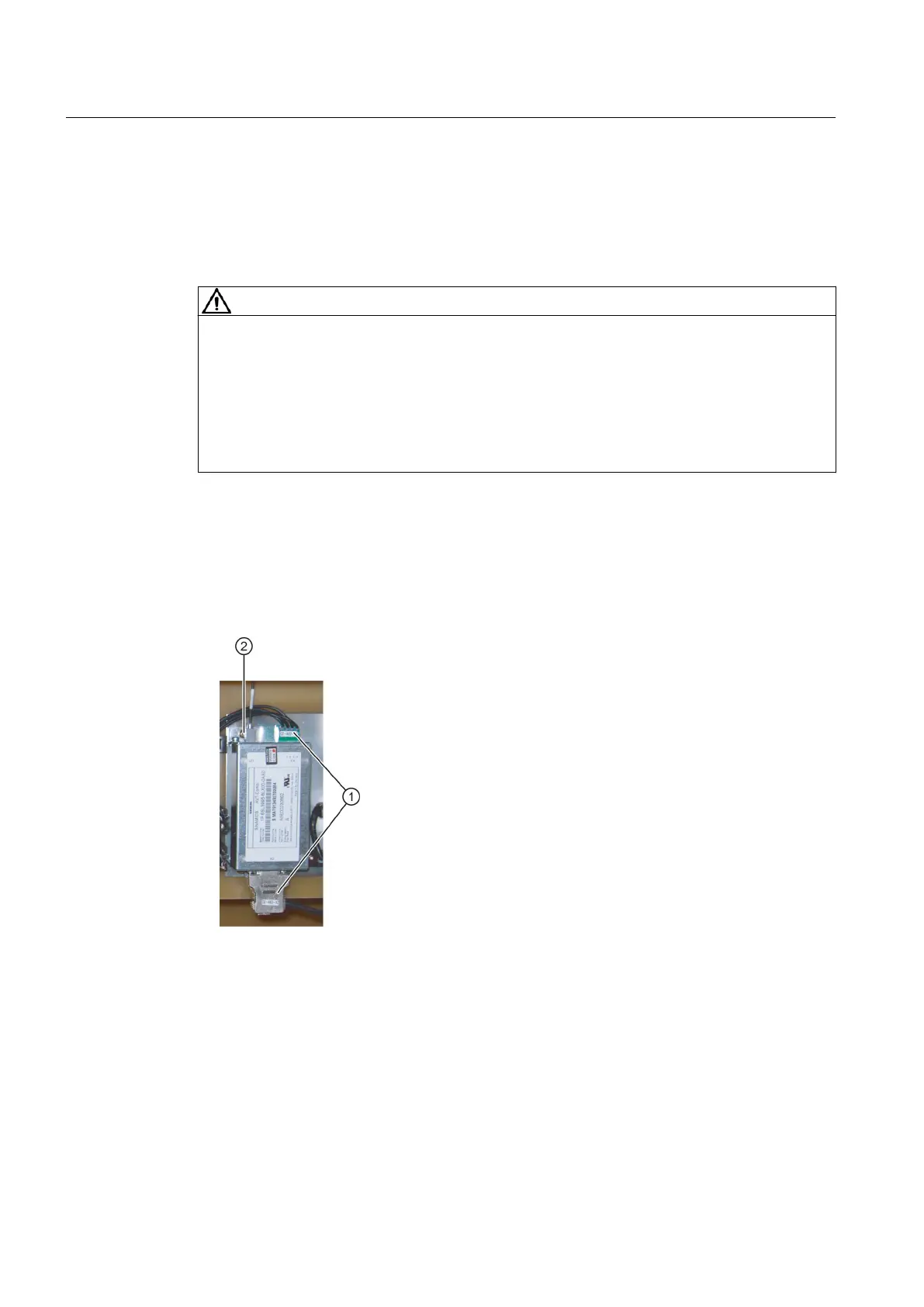
2. Release the control cables ①. Carefully ensure that you do not kink the fiber optic cables.
3. Remove the four fixing screws ② of the AVT combination module.
Figure 9-4 Example of an AVT combination module
Installing the AVT combination module
1. Use the screws ② to secure the AVT combination module.
2. Reconnect the control lines ①. Do not bend the fiber-optic conductors.
Maintenance
9.7 Repair
SINAMICS PERFECT HARMONY GH150 6SL38253AE412AA1-Z
118 Operating Instructions Rev.201910281231 EXAMPLE
 Loading...


