1. FUNCTIONS AND CONFIGURATION
1 - 17
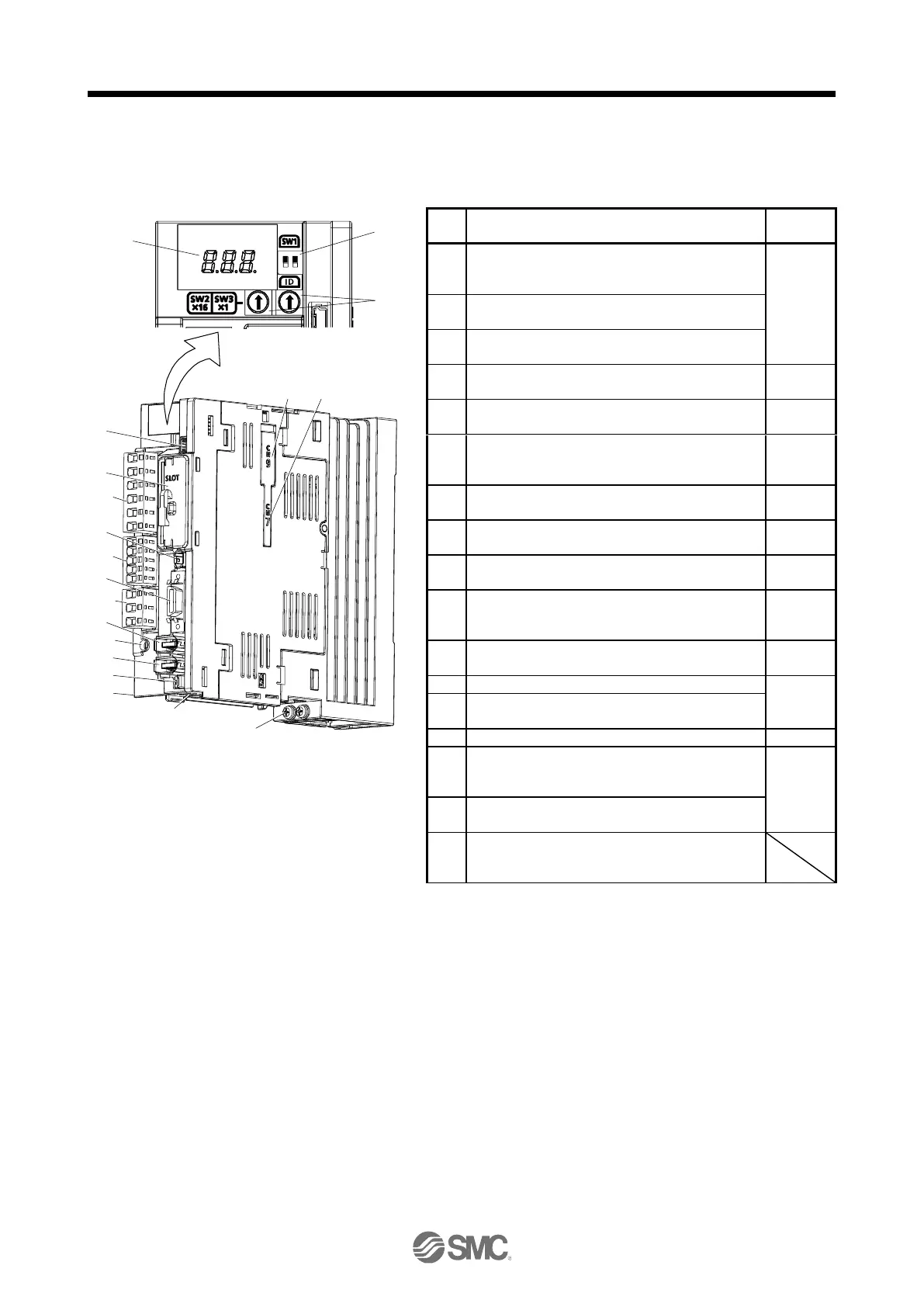
1.7 Structure
1.7.1 Parts identification
(1) LECSN2-T□
The diagram is for LECSN2-T5
1
ON
2
(1)
(2)
(3)
(7)
(10)
(13)
(9)
(17)
(6)
(5)
(11)
Bottom
(8)
(15)
(16)
(4)
(14)
Side
(12)
(18)(19)
Display
The 3-digit, 7-segment LED shows the servo status
and the alarm number.
Axis selection rotary switch (SW2/SW3)
Used to set the axis No. of driver.
Mode select switch (SW1)
Set the test operation mode. (SW1-1)
USB communication connector (CN5)
Connect with the personal computer.
I/O signal connector (CN3)
Used to connect digital I/O signals.
STO input signal connector (CN8)
Used to connect MR-J3-D05 safety logic unit and
external safety relay.
Network card slot (SLOT)
Insert the network card.
Encoder connector (CN2)
Used to connect the servo motor encoder.
External encoder connector (CN2L)
Do not use it.
Battery connector (CN4)
Used to connect the battery for absolute position
data backup.
Battery holder
Install the battery for absolute position data backup.
Protective earth (PE) terminal
Main circuit power connector (CNP1)
Connect the input power supply.
Control circuit power connector (CNP2)
Connect the control circuit power supply and
regenerative option.
Servo motor power output connector (CNP3)
Connect the servo motor.
Charge lamp
When the main circuit is charged, this will light.
While this lamp is lit, do not reconnect the cables.

 Loading...


