19.EtherNet/IP COMMUNICATION
19.6.8 Driver life diagnosis function
You can check the cumulative energization time and the number of on/off times of the inrush relay based on
the data in the driver. This function gives an indication of the replacement time for parts of the driver including
a capacitor and a relay before they malfunction. The information of the driver life diagnosis function can be
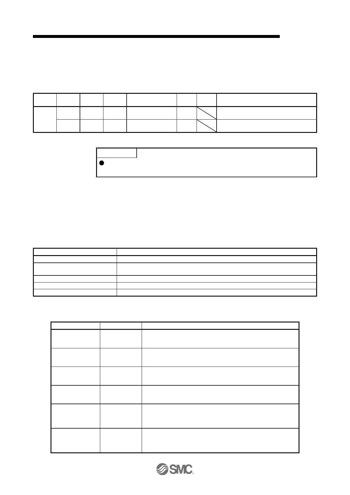
obtained with the following objects.
The cumulative energization time of the driver
is returned.
Number of inrush
relay on/off times
The number of on/off times of the inrush relay
of the driver is returned.
19.6.9 Positioning function by operation start-up signal
The positioning function by the operation start-up signal can be used in the
profile position mode.
19.6.9.1 Summary
The positioning function by the operation start-up signal performs positioning operations using external input
signals. Turning on Operation start-up signal activation (C_OSSA) in the profile position mode (pp) starts
positioning operations using external input signals.
Because positioning operations start using external input signals of the driver, an operation can be started
without delay at the start due to a communication delay.
19.6.9.2 Specification list
Standard control mode, fully closed loop control mode, linear servo motor control mode, DD
motor control mode
Single (A positioning operation is performed at the rising edge of an external input signal.)
Command generation pattern
A command pattern is calculated from the acceleration time and deceleration time.
19.6.9.3 Settings
(1) List of items set with parameters of the driver
Operation start-up
signal assignment
Set [Pr. PD38] to "_ _ 2 E" and assign ST (operation start-up) to an
external input signal. If Operation start-up signal activation (C_OSSA) is
turned on without ST assigned, Operation error (S_OERR) turns on.
S-pattern
acceleration/decelera
tion time constant
Set the time of the arc part for S-pattern acceleration/deceleration.
Setting "0" will make it linear acceleration/deceleration.
Set the maximum value of the target speed for the positioning operation.
This parameter can be set by inputting a value in Max profile velocity
(Class ID: 64h, Ins ID: 607Fh, Attr ID: 0).
Set the target speed for the positioning operation. This parameter can be
set by inputting a value in Profile velocity (Class ID: 64h, Ins ID: 6081h,
Attr ID: 0).
Acceleration time
constant
Set the acceleration time taken for the servo motor that has stopped to
reach the rated speed in the positioning operation. This parameter can
be set by inputting a value in Profile acceleration (Class ID: 64h, Ins ID:
6083h, Attr ID: 0).
Deceleration time
constant
Set the deceleration time taken for the servo motor that is operating at
the rated speed to stop in the positioning operation. This parameter can
be set by inputting a value in Profile deceleration (Class ID: 64h, Ins ID:
6084h, Attr ID: 0).

 Loading...


