3. SIGNALS AND WIRING
3 - 19
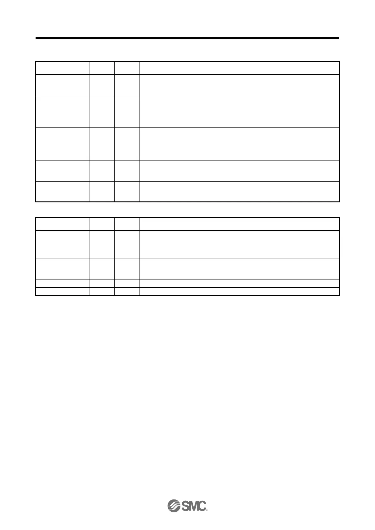
3.5.3 Output signal
Encoder A-phase
pulse (differential line
driver)
These devices output pulses of encoder output set in [Pr. PA15] and [Pr. PA16] in the
differential line driver type.
In CCW rotation of the servo motor, the encoder B-phase pulse lags the encoder A-
phase pulse by a phase angle of π/2.
The relation between rotation direction and phase difference of the A-phase and B-
phase pulses can be changed with [Pr. PC03].
Output pulse specification, dividing ratio setting, and electronic gear setting can be
selected.
Encoder B-phase
pulse (differential line
driver)
Encoder Z-phase
pulse (differential line
driver)
The encoder zero-point signal is output in the differential line driver type. One pulse is
output per servo motor revolution. This turns on when the zero-point position is
reached. (negative logic)
The minimum pulse width is about 400 μs. For home position return using this pulse,
set the creep speed to 100 r/min or less.
This is used to output the data set in [Pr. PC09] to between MO1 and LG in terms of
voltage.
Resolution: 10 bits or equivalent
This signal output the data set in [Pr. PC10] to between MO2 and LG in terms of
voltage.
Resolution: 10 bits or equivalent
Digital I/F power
supply input
Input 24 V DC (24 V DC ± 10% 300 mA) for I/O interface. The power supply capacity
changes depending on the number of I/O interface points to be used.
For sink interface, connect + of 24 V DC external power supply.
For source interface, connect - of 24 V DC external power supply.
Common terminal of input signal such as EM2 of the driver. This is separated from LG.
For sink interface, connect - of 24 V DC external power supply.
For source interface, connect + of 24 V DC external power supply.
Common terminal of MO1 and MO2.
Connect the external conductor of the shielded wire.

 Loading...


