3. SIGNALS AND WIRING
3 - 15
3.5 Signal (device) explanations
For the I/O interfaces (symbols in I/O division column in the table), refer to section 3.8.2.
The pin numbers in the connector pin No. column are those in the initial status.
3.5.1 Input device
(1) Input device pin
The following shows the input device pins and parameters for setting devices.
The on/off statuses of the pins can be read with "Digital inputs" of the object.
For details, refer to chapter 18,19,20.
(2) Input device explanations
Turn off EM2 (open between commons) to decelerate the servo motor to a stop
with commands.
Turn EM2 on (short between commons) in the forced stop state to reset that
state.
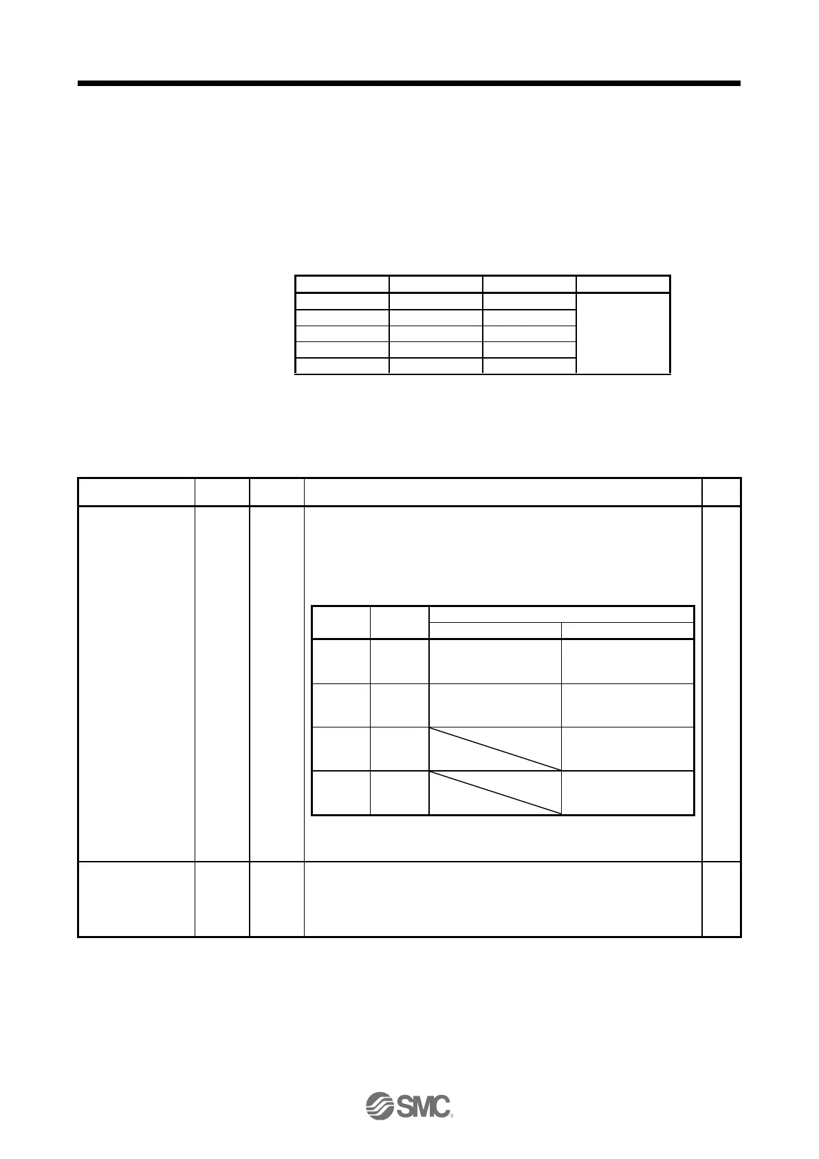
Set [Pr. PA04] to "2 1 _ _" to disable EM2.
The following shows the setting of [Pr. PA04].
MBR (Lock interlock)
turns off without the
forced stop deceleration.
MBR (Lock interlock)
turns off without the
forced stop deceleration.
MBR (Lock interlock)
turns off after the forced
stop deceleration.
MBR (Lock interlock)
turns off after the forced
stop deceleration.
MBR (Lock interlock)
turns off without the
forced stop deceleration.
MBR (Lock interlock)
turns off after the forced
stop deceleration.
EM2 and EM1 are mutually exclusive.
EM2 has the same function as EM1 in the torque mode.
When using EM1, set [Pr. PA04] to "0 0 _ _" to enable EM1.
When EM1 is turned off (open between commons), the base circuit shuts off,
and the dynamic brake operates to decelerate the servo motor to a stop.
The forced stop will be reset when EM1 is turned on (short between commons).
Set [Pr. PA04] to "0 1 _ _" to disable EM1.

 Loading...


