3. SIGNALS AND WIRING
3 - 14
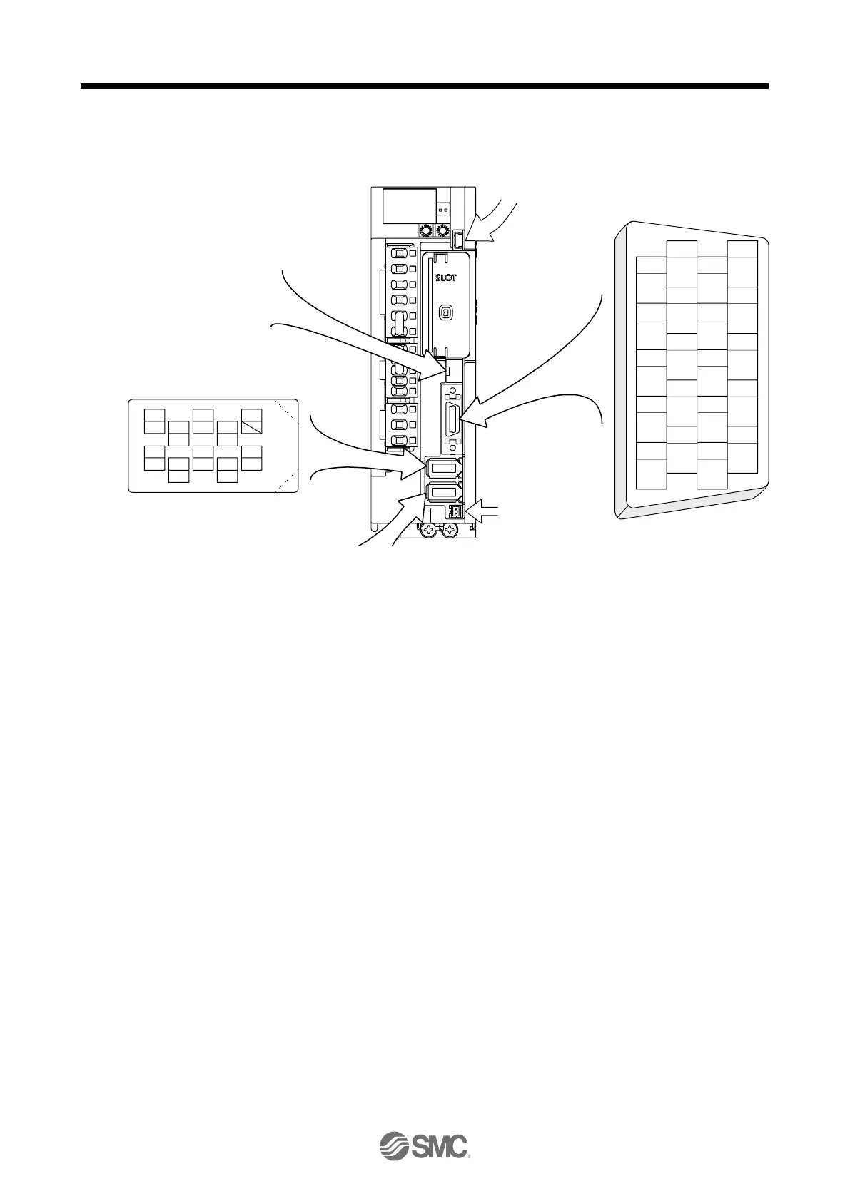
The driver front view shown is that of the LECSN
□
-T7 or less. Refer to chapter 9 DIMENSIONS for the
appearances and connector layouts of the other drivers.
CN5 (USB connector)
Refer to section 11.7
CN3
The frames of the CN2, CN2L, and CN3
connectors are connected to the protective
earth terminal in the servo amplifier.
CN4
(Battery connector)
Refer to section 11.8
1
2
3
5
4
6
7
9
8
10
11
12
13
14
15
16
17
18
19
20
LSP
MO1
TPR1
TPR2
DOCOM
DICOM
LZ
LSN
MO2
EM2
LG
MBR
LBR
LA
LB
LZR
LAR
ALM
DOG
INP
4
MRR
2
LG 8
6
1
P5
5
10
3
MR
7
9
BAT
MXR
MX
CN8
4
MRR2
2
LG 8
6
1
P5
5
10
3
MR2
7
9
MXR2
MX2
(Note) CN2L
4
PAR
2
LG 8
6
1
P5
5
10
3
PA
7
9
PB
PZR
PZ
PBR PSEL
(for using serial encoder)
(Note) CN2L
(for using A/B/Z-phase pulse encoder)
THM2
THM1
(Note) CN2
BAT
For the STO I/O signal
connector, refer to section 13.2.

 Loading...


