19.EtherNet/IP COMMUNICATION
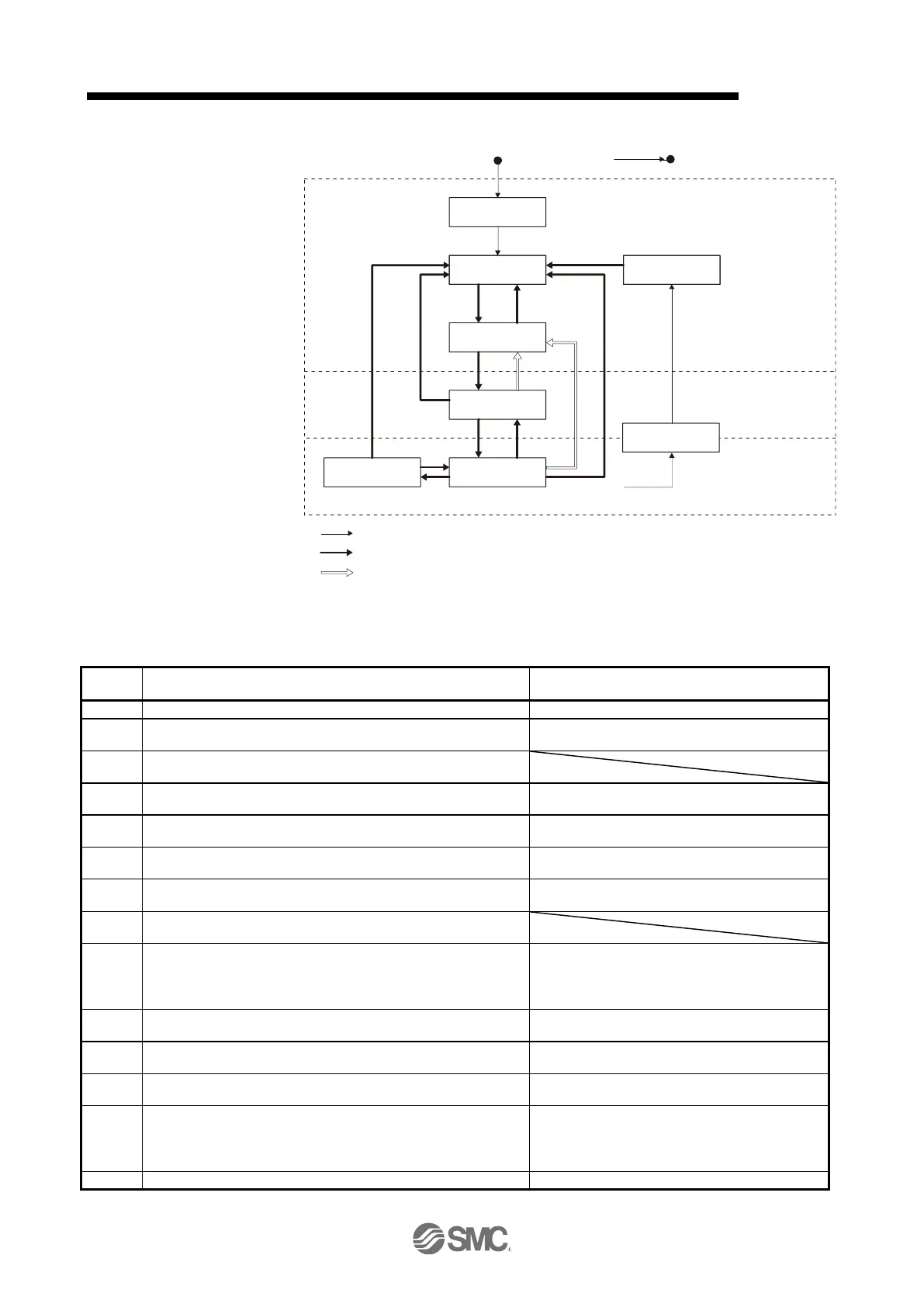
Not ready to
switch on
Sw itch on
disabled
Ready to
switch on
Sw itched on
Operation
enabled
Quick stop
active
(1)
(8) (9)
(10)
(0)
Power offPow er on
(2)
(3) (6)
(4) (5)
(7)
(15)
Error occurs
(11)
(12)
(13)
Fault
Fault reaction
active
(14)
(B): Ready-on, Servo-off
Transition by slave
Transition by master
Transition by slave or master
(A): Ready-off, Servo-off
(C): Ready-on, Servo-on
(16)
Figure 5.1 Transition between the FSA states
Table 5.1 State transition
The control circuit power supply is turned on.
The state automatically transitions when the control circuit power
supply is turned on.
The state transitions with the Shutdown command from the
master.
The state transitions with the Switch on command from the
master.
The state transitions with the Enable operation command from
the master.
The operation becomes ready after servo-on.
The state transitions with the Disable operation command from
the master.
The operation is disabled after servo-off.
The state transitions with the Shutdown command from the
master.
The state transitions with the Disable Voltage command or Quick
Stop command from the master.
(a) The state transitions with the Shutdown command from the
master.
(b) The state transitions when the main circuit power supply is
turned off.
Operation is disabled after servo-off or RA-off.
The state transitions with the Disable Voltage command from the
master.
Operation is disabled after servo-off or RA-off.
The state transitions with the Disable Voltage command or Quick
Stop command from the master.
The state transitions with the Quick Stop command from the
master.
(a) The state automatically transitions after Quick Stop is
completed. (If the Quick Stop option code is 1, 2, 3, or 4)
(b) The state transitions with the Disable Voltage command from
the master.
Operation is disabled after servo-off or RA-off.
Processing against the alarm is executed.

 Loading...


