10
EN
ATYSt - 541995C - SOCOMEC
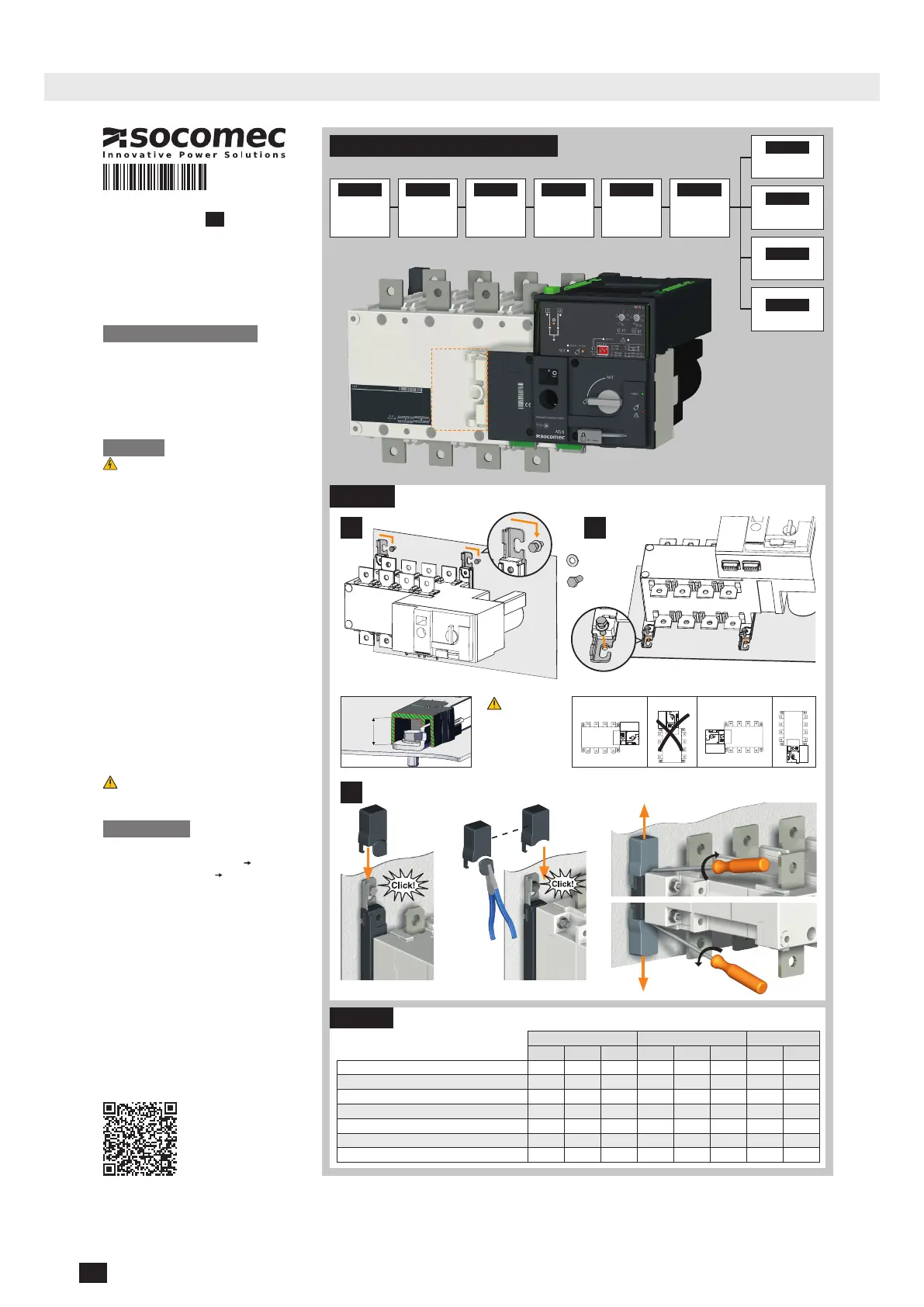
4. QUICK START
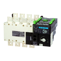
4.1. Quick Start ATySt Frame B3 to B5 (125 A to 630 A)
QUICK START
125 A-630 A
ATyS t
1
3
2
Max.
0.51 in.
13 mm.
125 A 160 A 200 A 250 A 315 A 400 A 500 A 630 A
35 35 50 95 120 185 2x95 2x120
- - - - - - 2x32x5 2x40x5
50 95 120 150 240 240 2x185 2x300
25 25 25 32 32 32 50 50
M8 M8 M8 M10 M10 M10 M12 M12
73.46/8.3 73.46/8.3 73.46/8.3 177.02 /20 177.02 /20 177.02 /20 354.04/40 354.04/40
115.06/13 115.06/13 115.06/13 230.13/26 230.13/26 230.13/26 398.30/45 398.30/45
FRAME B3 FRAME B4 FRAME B5
Minimum cable section Cu (mm
2
)
Recommended Cu busbar cross-section (mm²)
Maximum Cu cable cross-section (mm²)
Maximum Cu busbar width (mm)
Type of screw
Recommended tightening torque(lb.in/N.m)
Maximum tightening torque (lb.in/N.m)
Preliminary operations
Check the following upon delivery and after removal of the
packaging:
- Packaging and contents are in good condition
- The product reference corresponds to the order
- Contents should include:
Qty 1 x ATyS t
Qty 1 x Emergency handle and fixing clip
Quick Start instruction sheet
Warning
Risk of electrocution, burns or injury to persons and /
or damage to equipment.
This Quick Start is intended for personnel trained in the
installation and commissioning of this product. For further
details refer to the product instruction manual available on
the SOCOMEC website.
• This product must always be installed and
commissioned by qualified and approved personnel.
• Maintenance and servicing operations should be
performed by trained and authorised personnel.
• Do not handle any control or power cables connected to
the product when voltage may be, or may become
present on the product, directly through the mains or
indirectly through external circuits.
• Always use an appropriate voltage detection device to
confirm the absence of voltage.
• Ensure that no metal objects are allowed to fall in the
cabinet (risk of electrical arcing).
- For 125 - 160 A (Uimp = 8 kV). Terminations must respect
a minimum of 8 mm clearance from live parts to parts
intended to be earthed and between poles.
- For 200 - 630 A (Uimp = 12 kV). Terminations must respect
a minimum of 14 mm clearance from live parts to parts
intended to be earthed and between poles.
Failure to observe good enginering practises as well as to
follow these safety instructions may expose the user and
others to serious injury or death.
Risk of damaging the device
In case the product is dropped or damaged in any way it is
recommended to replace the complete product.
Accessories
• Bridging bars and connection kits.
• Control voltage transformer (400 VAC
230 VAC).
• DC power supply (12/24 VDC
230 VAC).
• Phase barriers.
• Terminal shrouds.
• Terminal screens.
• Auxiliary contacts (Additional).
• Padlocking in 3 positions (I - O - II).
• Lockout accessories (RONIS - EL 11 AP).
• Door escutcheon frame.
• ATyS D10 Interface (remote display).
• Voltage sensing kit.
• Sealable cover.
• RJ45 cable for ATyS D10.
For further details refer to the product instruction manual
under chapter "Spares and Accessories"
www.socomec.com
To download, brochures, catalogues
and technical manuals:
https://www.socomec.com/range-
automatic-transfer-switches_
en.html?product=/atys-t-atys-g_
en.html
549647C
Motorised Source Changeover Switch
Automatic Transfer Switching Equipment
EN
STEP 1
Cabinet / Back
Plate Installation
STEP 3
COMMAND /
CONTROL
terminal
connections
STEP 2
Power Terminal
Connections
STEP 4
Power SUPPLY and
ATS Controller
Terminal
Connections
STEP 5
CHECK
STEP 6
PROGRAMMING
STEP 7A
AUT Mode
(Automatic Control)
STEP 7C
Manual Mode
STEP 7B
AUT Mode
(Remote Control)
STEP 7D
Padlocking Mode
Installation and Commissioning
Installation
500 A, 630 A.125 A to 400 A.
Power Terminal Connections
M8 Type Z
M8
Caution: ensure
that the product is
installed on a flat
rigid surface.
Recommended
orientation
OKOK
STEP 1
STEP 2
Clip for
storage of
the
emergency
handle
Mounting
Removing covers
To be connected using terminal lugs, rigid or flexable
busbars.
 Loading...