50
EN
ATYSt - 541995C - SOCOMEC
8.2. Electrical operation
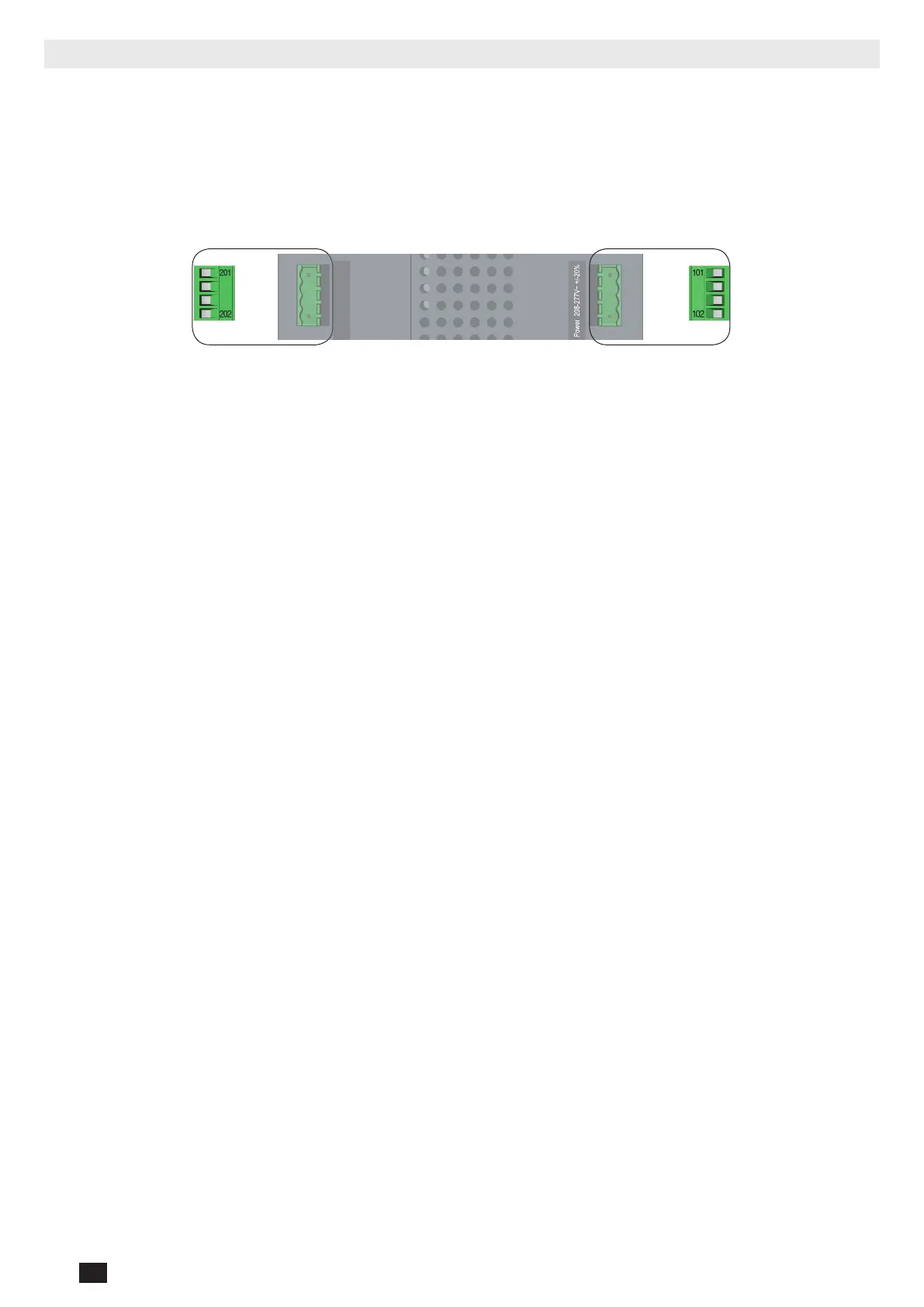
8.2.1. Dual power supply
The ATySt includes a dual power supply and is to be powered between terminals 101 - 102 and 201 – 202 (2 different supplies
- main & alternative) within the limits of: 2x 208 – 277VAC ± 20% / (166 – 332VAC) / 50/60Hz ± 10%.
Current Input: 100mA (Standby mode) / 15A max (Switching mode)
Surge Protection: Vin_sg: 4.8KV – 1.2/50µs according to IEC 61010-1
Terminal connectors: Minimum 1.5mm² / Maximum 2.5mm²
Dual auxiliary supply:
Uc 208-277V~ +/-20% 50/60Hz
Power comsumption: 22VA
See instruction sheet
ATS CONTROLLER
To D10
To D20
64B 63B
64B 63B
417 416 415 414 413
207 208 209 210
417 416 415 414 413
207 208 209 210
7172 74
7172 74
ATyS t
Dual auxiliary supply:
Uc 208-277V~ +/-20% 50/60Hz
Power comsumption: 22VA
See instruction sheet
ATS CONTROLLER
ATyS p
Dual auxiliary supply:
Uc 208-277V~ +/-20% 50/60Hz
Power comsumption: 22VA
See instruction sheet
ATS CONTROLLER
ATyS g
Dual auxiliary supply:
Uc 208-277V~ +/-20% 50/60Hz
Power comsumption: 22VA
See instruction sheet
ATS CONTROLLER
To D10
To D20
64B 63B
64B 63B
417 416 415 414 413
207 208 209 210
417 416 415 414 413
207 208 209 210
7172 74
7172 74
ATyS t
Dual auxiliary supply:
Uc 208-277V~ +/-20% 50/60Hz
Power comsumption: 22VA
See instruction sheet
ATS CONTROLLER
ATyS p
Dual auxiliary supply:
Uc 208-277V~ +/-20% 50/60Hz
Power comsumption: 22VA
See instruction sheet
ATS CONTROLLER
ATyS g
201-L/N
202-N/L
101-L/N
102-N/L
Aux Supply-2
Power
208-277 Vac ±20%
(166-332Vac 50/60 Hz)
Aux Supply-1
Power
208-277 Vac ±20%
(166-332Vac 50/60 Hz)
8.2.2. Voltage sensing inputs
The ATySt includes dual single phase and three phase voltage sensing (terminals 103 - 106 and 203 - 206)
designed to monitor 1Phase (L-N) supplies of up to 332Vac and 3 phase (L-L) of up to 575/600Vac.
The ATySt is designed to handle single phase, three phase with neutral as well as three phase without neutral
networks. Simply dene the correct conguration of single or three phase and with or without neutral using dip
switches (positions A/B, C/D) on the front of the ATS controller.
Sensing connections are usually tapped directly off the ATySt power terminals using the ATyS sensing kit available
as an accessory. Sensing kits are available with the neutral on the left or neutral on the right to match the network
conguration where the ATyS will be operating. Refer to the ATyS accessory section for more details.
Sensing values measured will have a direct inuence on determining the availability of the main and the alternative
supplies as well as the ATySt automation.
The parameters monitored through sensing are the following:
• Phase rotation / imbalance (3 phase networks)
Phase imbalance in the ATySt is relative to the nominal voltage congured with auto conf together with the
hysteresis set in position G/H (10/20%) with dip switch 4.
• Frequency within set limits
This will depend on the nominal frequency congured using auto conf together with the hysteresis set in position
G/H (5/10%) with dip switch 4.
• Loss of Neutral
When used on three phase + neutral applications (congured with dip switch 1 set on position A and dip switch
2 set on position C, the loss of neutral will be detected for most unbalanced loads. Detection will be done when
the load is on.
• Loss of the main or alternative supply.
Loss of supply depends on the nominal voltage and frequency congured using auto conf together with
the hysteresis set in position G/H (10/20% for ΔU and 5/10% for ΔF) with dip switch 4. The supply will be
considered as failed after the failure timer (set through potentiometer FT on the ATS controller) has elapsed. The
FT setting is adjustable from 0 – 60 seconds.
• Return of main and / or alternative supply.
Return of supply depends on the nominal voltage and frequency congured using auto conf together with
the hysteresis set in position G/H (10/20% for ΔU and 5/10% for ΔF) with dip switch 4. The supply will be
considered as returned after the return timer (set through potentiometer RT on the ATS controller) has elapsed.
The RT setting is adjustable from 0 – 60 minutes.
Measurement accuracy: Frequency: 0.1% - Voltage: 1%
 Loading...