42
EN
ATYSt - 541995C - SOCOMEC
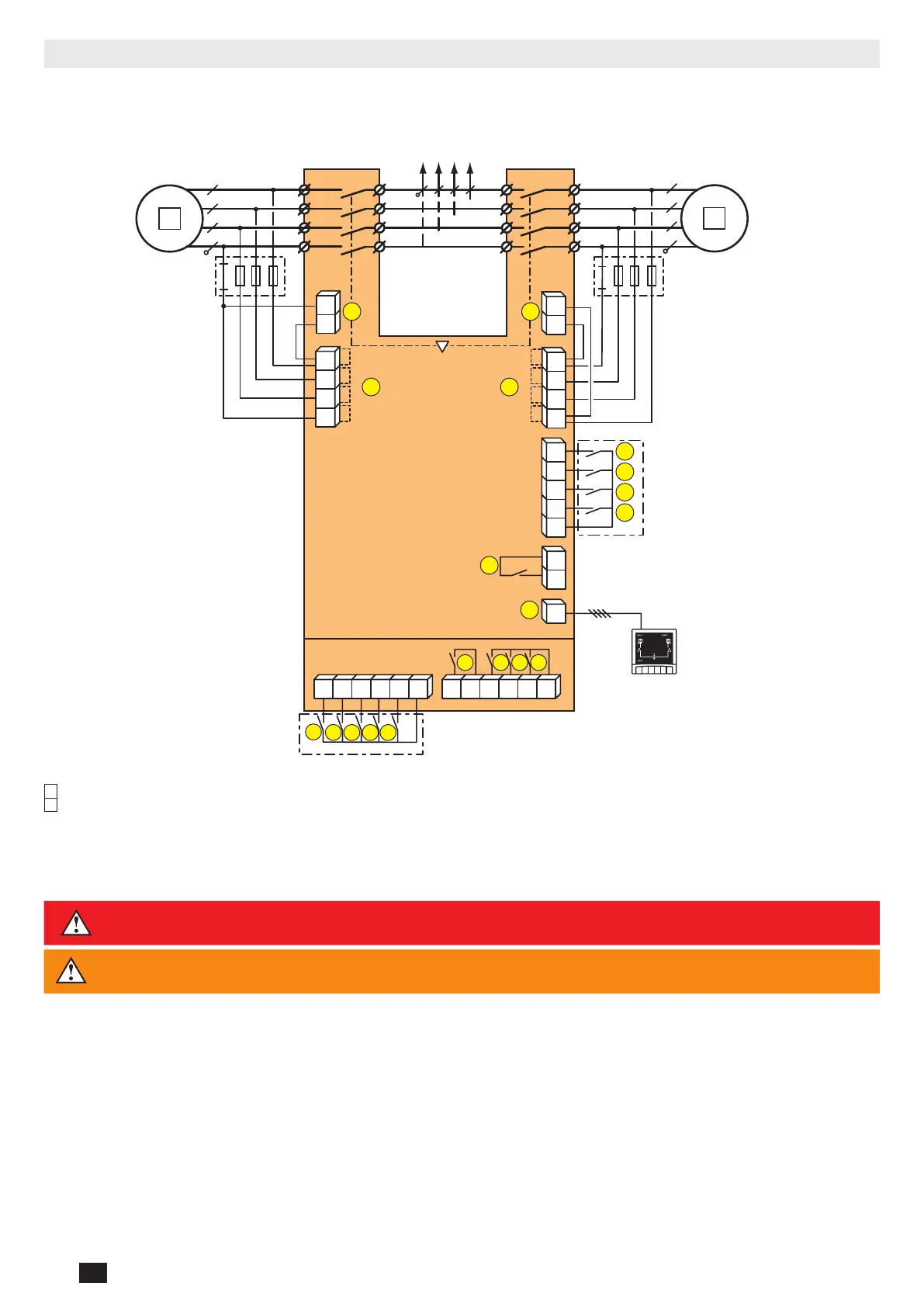
7.3. Control circuits
7.3.1. Typical ATySt wiring
Example: Control wiring for a 400VAC application having a 3 phase and neutral supply.
5
6
4
3
2 1
2
7
104 103
312313 314315 316317 63A64A 24 14 04 13
8 9
10
RJ
102 101
105106
414 413415416417
64B 63B
201 202
205 206204203
15
14
13
12
11
16
16
17
17
1
F1
F2
I/1-2 I/3-4 I/5-6 I/7-8
II/1-2 II/3-4 II/5-6 II/7-8
D10
Remote
Display Unit
Fus. 4A
type gG
Fus. 4A
type gG
ATySt Voltage
Sensing and Power
supply Kit (excludes
the need for fuses
F1 & F2
1
preferred source
2
alternate source
1. Position 0 order
2. Position I order
3. Position II order
4. Zero position priority order
5. Remote Control Enable (Priority over Auto)
6. Product Available output (Motor)
7. Position II aux contact
8. Position I aux contact
9. Position 0 aux contact
10. O/P to D10 remote display
11. Product Available output (ATS)
12. I/P Inhibition of the ATS controls
13. I/P Manual retransfer (RTC)
14. I/P to define the source priority: Source priority
set to S2 if closed, S1 if open
15. I/P with/without source priority: nosource
priority when closed
16. Voltage sensing inputs
17. Power supply Inputs
DANGER
Do not handle any control or power cables connected to the ATyS when voltage may be
present.
CAUTION
Verify that the Auxiliary power supply feeding terminals 101 and 102 / (201 and 202) are within
the limits of 208VAC -> 277VAC ±20%
 Loading...