54
EN
ATYSt - 541995C - SOCOMEC
8.2.4. Fixed outputs - Dry contacts
8.2.4.1. Description
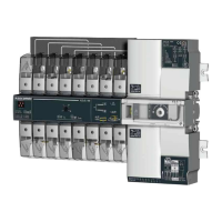
As standard, the ATySt is equipped with four xed outputs located on the
motorisation module.
(Dry contacts to be powered by the user).
8.2.4.2. Position auxiliary contact
The ATySt is equipped with integrated position (I – O – II) auxiliary contact outputs through 3 off micro switches.
Pins 13, 04, 14, 24
(Normally Open contacts with pin 13 as common)
8.2.4.3. ATySt Product available output (motorisation)
Pin 63A – 64A
(Normally Open contact that is held closed when the motorisation is available).
This contact gives constant feedback about the product’s availability and it’s capacity to transfer from the main supply to the
alternative. The feedback given is relative to the motorisation module excluding the ATS controller that may be monitored
separately.
The ATySt performs a self diagnostics test on the motorisation module at startup, when put from Manual -> Auto and then
every 5 minutes. This test ensures that the ATySt is operational in terms of control inputs. Should one of the tests fail, a
second test is performed to reconrm the error state.
Should the ATySt motorisation module become unavailable, contact 63A – 64A are opened, the power/ready LED’s are
switched off, and the fault LED is activated. The fault LED will remain active for as long as sufcient power is available and the
fault condition is not reset. The fault is reset when the product is switched from AUT -> Manual -> Auto mode.
ATySt (Motorisation) Product Available / Unavailable Watchdog relay will open for any of the following reasons below: For
added security, “Product Availability” is informative and does not necessarily inhibit motor operation.
Product Unavailable + Warning LED Condition: Inhibition
Product in manual mode Yes
Motor not detected (Autotest) No
Control voltage out of range Yes
Operating factor fault active (N° of operations / min) Yes
Powerfail active Yes
Customer input autotest failed No
Invalid product customisation No
Abnormal switching when not in manual mode Yes
Requested position not reached Yes
Locked mode active when not in manual mode Yes
External Fault -> User input No
Unexpected current owing through the motor when idle Yes
Sampling rate for the above is every 10 ms
Exception: motor detection sampling rate is every 5 min
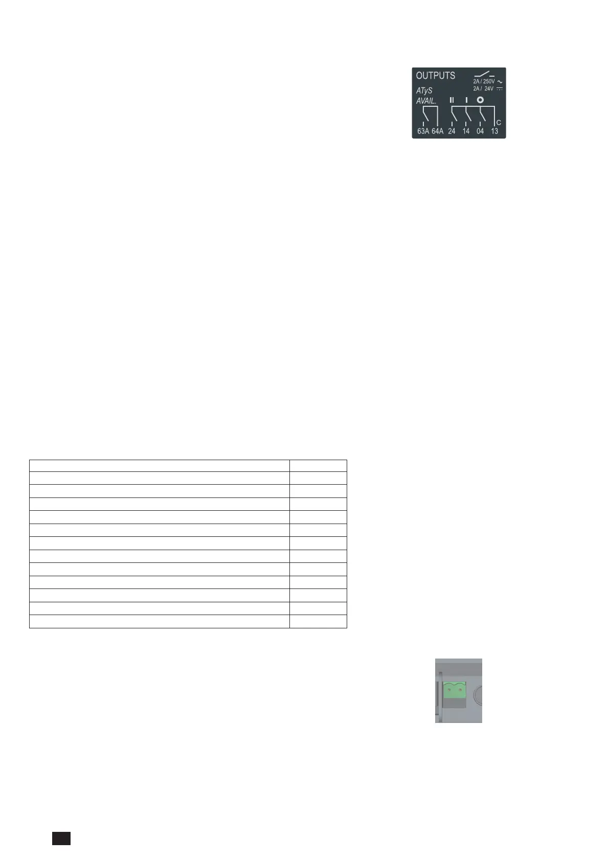
Pin 63B – 64B
ATySt Product Available Output (ATS module)
(Normally Open contact that is held closed when the ATS is available)
The above contacts may be used separately for precise monitoring of the state
of each module or wired in series to monitor the availability of the ATS and
motorisation modules as a complete unit.
Dual auxiliary supply:
Uc 208-277V~ +/-20% 50/60Hz
Power comsumption: 22VA
See instruction sheet
ATS CONTROLLER
To D10
To D20
64B 63B
64B 63B
417 416 415 414 413
207 208 209 210
417 416 415 414 413
207 208 209 210
7172 74
7172 74
ATyS t
Dual auxiliary supply:
Uc 208-277V~ +/-20% 50/60Hz
Power comsumption: 22VA
See instruction sheet
ATS CONTROLLER
ATyS p
Dual auxiliary supply:
Uc 208-277V~ +/-20% 50/60Hz
Power comsumption: 22VA
See instruction sheet
ATS CONTROLLER
ATyS g
 Loading...