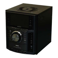
HCD-PZ1D
20
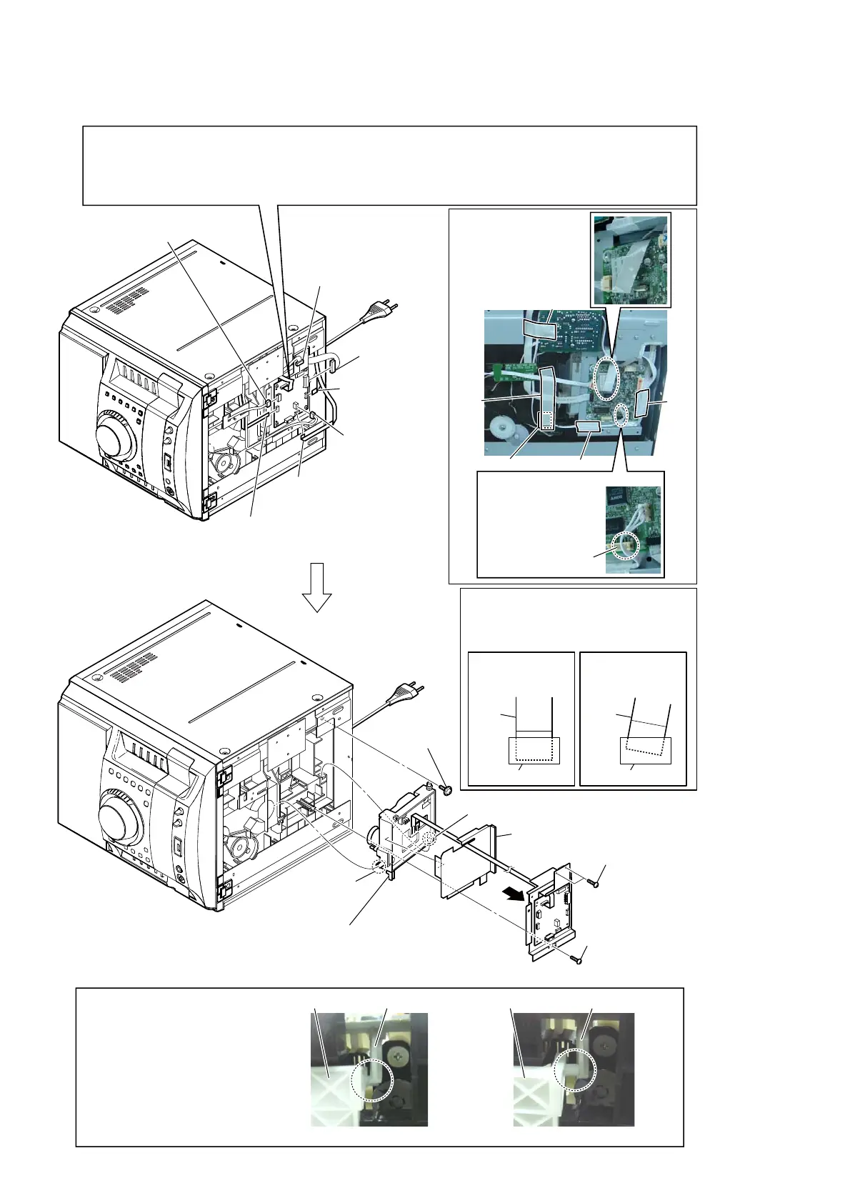
2-19. BU HOLDER BLOCK
– Bottom side view –
qs floating
screw
(PTPWH M2.6)
qa dust cover (BU)
qd shaft
qf cam shaft
8 two screws
(BVTP 3 u8)
9 screw
(BVTP 2.6 (3CR))
4 wire (flat type) (9 core)
(CN1106)
3 flexible flat cable (7 core)
(CN1104)
6 wire (flat type)
(7 core)
(CN4602)
1 connector
(CN1105)
2 connector
(CN1103)
5 connector
(CN601)
7 connector
(CN201)
:iUe settiQJ
CN101
Tape
Note 2:
Process the wire
straight so as not
to touch on the
connector.
NG
Tape
Tape
Tape
Tape
0
Perform work with this wire (flat type) (24 core) connected, or make a bridge as mentioned above and then disconnect
the wire (flat type) (24 core). (Optical pick-up will be destroyed without bridging.)
On the contrary at the installation, connect the wire (flat type) (24 core) first, and then remove the bridge.
Note 1:
For a soldering iron, use the one with a ground wire. (Refer to DISASSEMBLY 2-19. DMB19 BOARD)
35(&$87,2N :+(N 5(029,NG :,5( )/$7 7<3( &25(
qg
BU holder block
Note 4:
When you disassemble the BU holder block,
confirm the holder (310) assy is a normal
position.
holder (310) assylever (lifter (H)) holder (310) assy
Note 5:
When you install the BU holder
block, hang the holder (310) assy
on the lever (lifter (H)).
OK NG
lever (lifter (H))
Note 3:
When you install the flat cable, please
install them correctly.
There is a possibility that this machine
damages when not correctly installing it.
Insert is straight
to the interior.
connector
Insert is incline
flexible
cable
connector
flexible
cable
OK NG
 Loading...


