39
Power Supply and Connectors
Chapter 2 Names and Functions of Parts
5
Enter the page number for the menu you want to
register.
To register the currently displayed menu
1
In the Home >Favorites >Shortcut menu (0021), select
the group to which you want to register the menu
beforehand.
2
Display the menu you want to register in the shortcut
menu.
3
Press the menu page number button, and press [Add
Favorite].
The menu selected in step 2 is automatically registered
to an open button in the group selected in step 1.
Customizing the shortcut menu
To customize buttons
1
In the Home >Favorites >Shortcut menu (0021), press
[Button Edit].
The Home >Favorites >Button Edit menu (0023)
appears.
2
Use the following procedures.
To rename the button
Select the button you want to change, press [Rename],
enter a new button name (up to 24 characters), and
then press [Enter].
To change the button color
Select the button you want to change, press [Color
Set], and then select the desired color.
To copy button settings
Select the button you want to copy, press [Copy], and
then select the target button and press [Paste].
To delete button settings
Select the button you want to delete, then press
[Clear].
To customize groups
1
In the Home >Favorites >Shortcut menu (0021), press
[Group Edit].
The Home >Favorites >Group Edit menu (0022)
appears.
2
Use the following procedures.
To rename a group
Select the group you want to change, press [Rename],
enter a new group name (up to 24 characters), and then
press [Enter].
To copy group settings
Select the group you want to copy and press [Copy],
and then select the target group and press [Paste].
To delete group settings
Select the group button you want to delete, press
[Clear]. Check the message, then press [Yes].
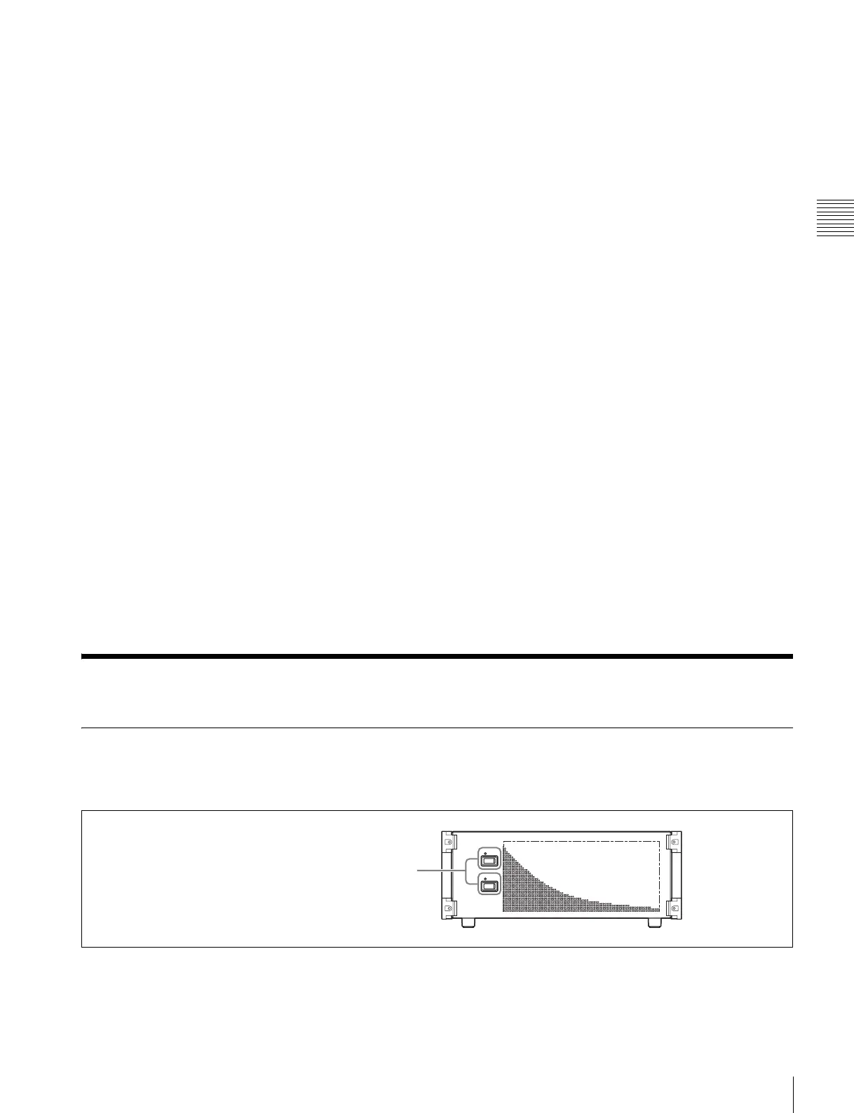
Power Supply and Connectors
MVS-3000 Multi Format Switcher Processor
Front panel
POWER A, B switches and status indicators
The POWER switches turn the unit on and off. The unit is
powered on when the POWER switches are on the “ ? ”
side, and powered off when the POWER switches are on
the “a” side. The status indicators light in green when the
unit is powered on.
Operation continues as long as power supply is normal on
one unit.
POWER A, B switches and status indicators
 Loading...


