11
LED Color
Description
POWER Green
The control circuit power supply is supplying power.
OPERATI-
ON
White
Inverter is in stop mode.
Green
Inverter is in grid-connected run mode.
Yellow Inverter is in alarm run mode.
FAULT Red
A fault occurs and has not been removed.
The indicator will be off when the fault is cleared.
Buttons
The functions of each button are shown in the table below.
Button Description
DC Turn this knob switch to disconnect/connect the DC switch
EMERGENCY STOP When an emergency occurs, the DC load break switches and AC
circuit breakers disconnect automatically after pressing the
emergency stop button.
The MAINTENANCE INTERFACE
The cover plate of the LCD can only be opened with the key. Remove the key and store it
properly after use.
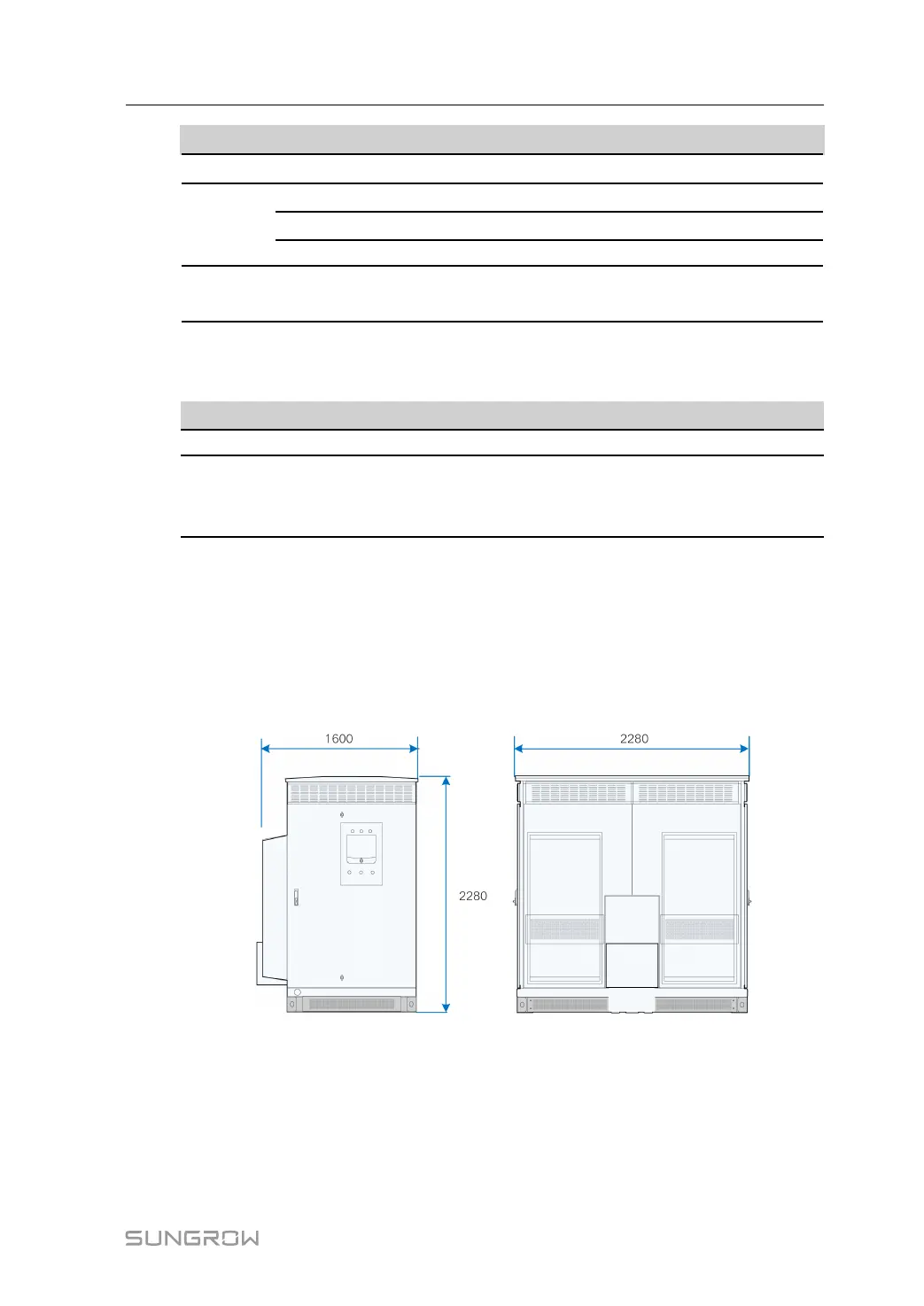
3.1.2 Mechanical Parameter
Dimensions
External dimensions are shown in the figure below.
Clearance Spaces
The clearances around the inverter should be sufficient for the doors to be opened
System Manual 3 Product Description
 Loading...