33
6.2.3 Opening the Cable Entries
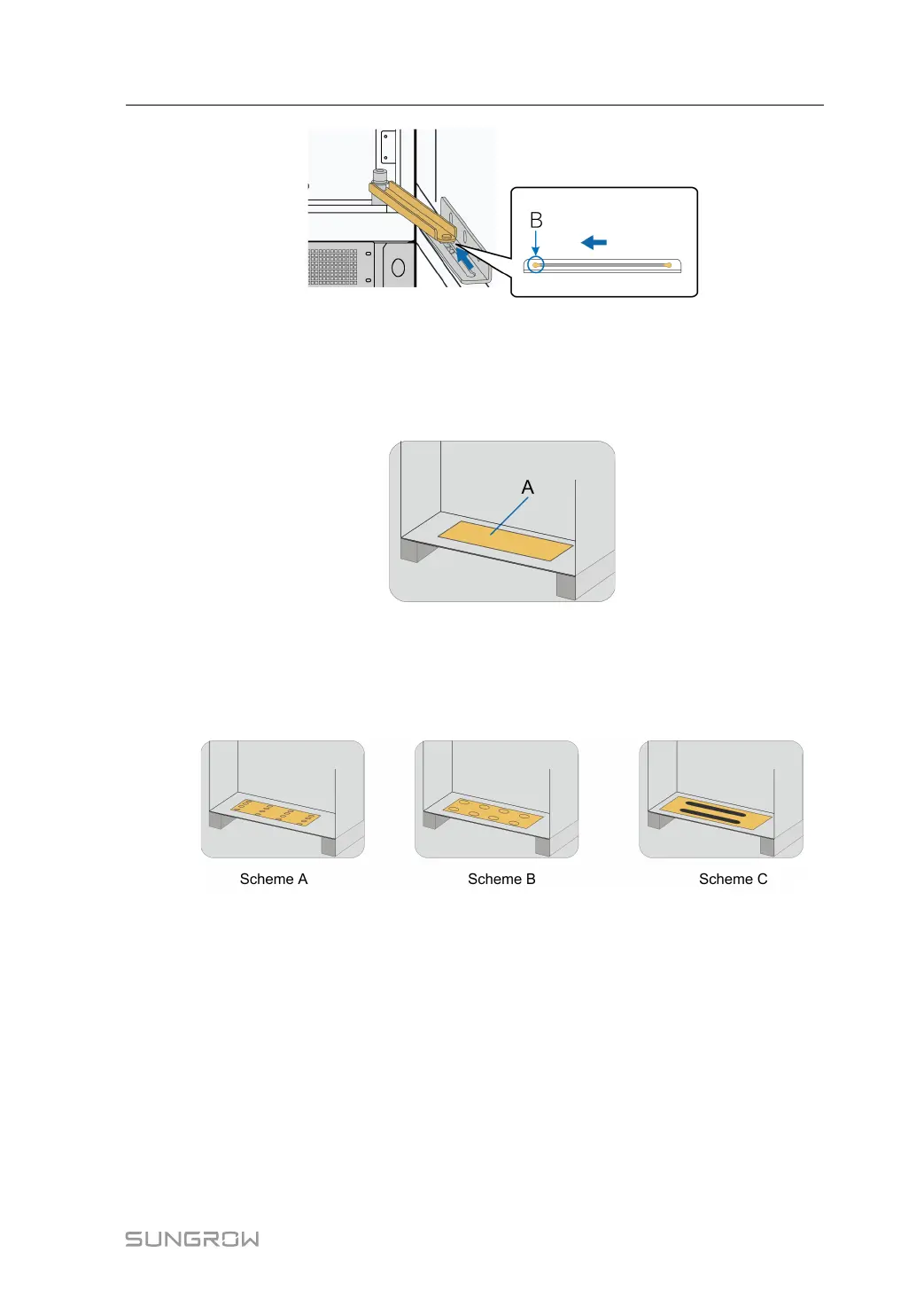
Drilling Procedure
step 1 Locate the cable entry at the bottom of the inverter. For example, the location of the DC
cable entry is shown as A in the following figure.
step 2 Drill holes on the cover plate at the bottom of the inverter.
- - End
Drilling Schemes
The following three drilling schemes are provided for reference.
Further Operations
When performing cable connection, take corresponding measures to protect the cables from
being scratched or damaged by the holes drilled.
After finishing cable connection, use waterproof and fireproof materials to seal gaps around
the cables to prevent rodents from entering, affecting normal operation.
System Manual 6 Electrical Installation
 Loading...