FI SYSTEM/ CVT SYSTEM 6-31
“C14” TP SENSOR CIRCUIT MALFUNCTION
INSPECTION
DETECTED CONDITION POSSIBLE CAUSE
Output voltage low or high. • TP sensor maladjusted.
• TP sensor circuit open or short.
• TP sensor malfunction.
• ECM malfunction.
( )
0.20 V Sensor voltage
4.80 V
<
without the above range.
1
1
V
V
1
2
Ω
Ω
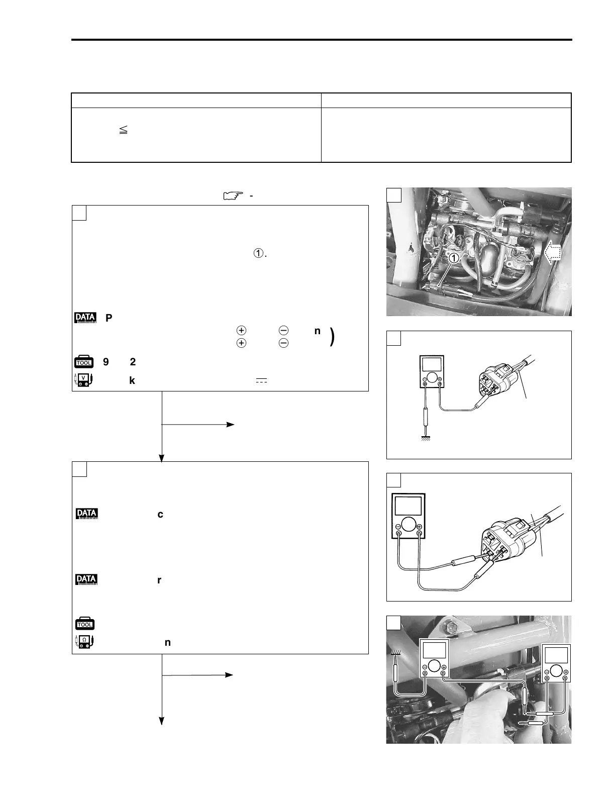
Turn the ignition switch OFF.
Check the TP sensor coupler for loose or poor contacts.
If OK, then measure the TP sensor input voltage.
Disconnect the TP sensor coupler
1
.
Turn the ignition switch ON.
Measure the voltage at the Red wire and ground.
If OK, then measure the voltage at the Red wire and B/Br
wire.
• Remove the maintenance lid. (
:
9-13)
1
2
Ye s
Ye s
No
No
Reset the TP sensor
position correctly.
Replace the TP sensor
with a new one.
;
TP sensor input voltage: 4.5 – 5.5 V
+
Red –
-
Ground
+
Red –
-
B/Br
z
09900-25008: Multi circuit tester
u
Tester knob indication: Voltage (
-
)
( )
Loose or poor contacts on
the ECM coupler.
Open or short circuit in the
Red wire or B/Br wire.
Turn the ignition switch OFF.
Disconnect the TP sensor coupler.
Check the continuity between Yellow wire and ground.
;
TP sensor continuity: ∞ Ω (Infinity)
(Yellow wire – Ground)
If OK, then measure the TP sensor resistance at the
coupler (between Yellow and Gr or R wires).
Turn the throttle grip and measure the resistance.
;
TP sensor resistance
Throttle valve is closed : Approx. 1.1 kΩ
Throttle valve is opened : Approx. 4.2 kΩ
z
09900-25008: Multi circuit tester
t
Tester knob indication: Resistance (Ω)
Red
Ground
Red
B/Br

 Loading...