COOLING AND LUBRICATION SYSTEM 8-11
INSPECTION
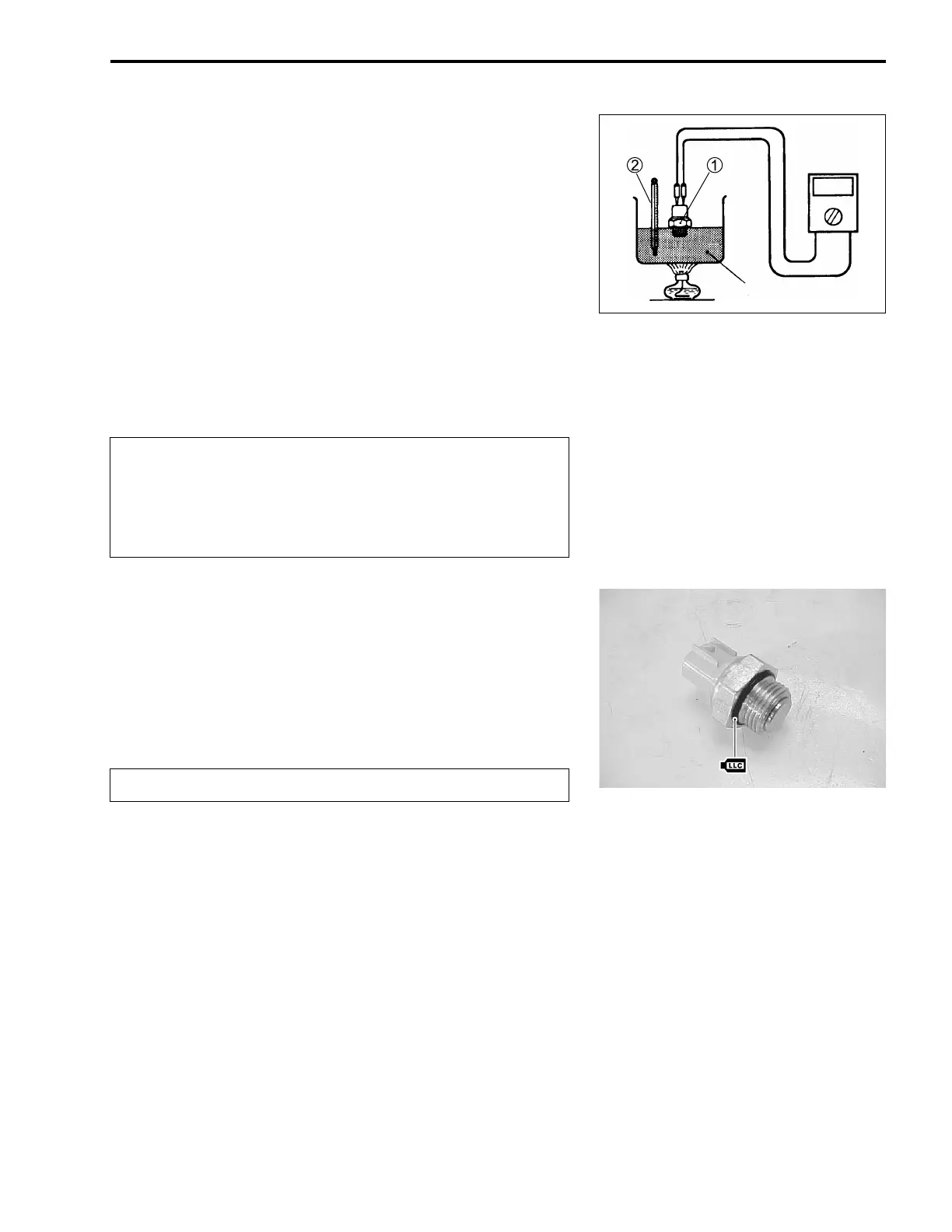
• Check the thermo-switch closing or opening temperatures by
testing it at the bench as shown in the figure. Connect the
thermo-switch
1 to a circuit tester and place it in the oil con-
tained in a pan, which is placed on a stove.
• Heat the oil to raise its temperature slowly and read the col-
umn thermometer
2 when the switch closes or opens.
[ 09900-25008: Multi circuit tester set
< Tester knob indication: Continuity test (>)
Cooling fan thermo-switch operating temperature
Standard (OFF→
→→
→ON): Approx. 98°C (208°F)
(ON→
→→
→OFF): Approx. 92°C (198°F)
INSTALLATION
Install the cooling fan thermo-switch in the reverse order of
removal. Pay attention to the following points:
• Apply engine coolant to the O-ring.
• Tighten the cooling fan thermo-switch to the specified torque.
! Cooling fan thermo-switch: 17 N·m (1.7 kgf-m, 12.3 lb-ft)
• Pour engine coolant. (2-21)
• Bleed air from the cooling circuit. (2-21)
Oil
* Take special care when handling the cooling fan
thermo-switch. Do not subject it to strong blows or
allow it to be dropped.
* Do not contact the cooling fan thermo-switch
1 and
the column thermometer
2 with a pan.
Replace the removed O-ring with a new one.