TM8100/TM8200 Service Manual Disassembly and Reassembly 137
© Tait Electronics Limited June 2006
5.3 Reassembling the Radio Body
Inspect all disassembled parts for damage and replace them, if necessary.
Reassembling the
Main-Board
Assembly
The circled numbers in this section refer to the items in Figure 5.4 on
page 135. This figure shows the 40W/50W configuration.
1. If the power connector has been replaced:
■ With the 40W/50W radio, use a Torx T6 torque-driver to
tighten the two screws
C to 1lb·in (0.11N·m).
■ With the 25W radio, use a Torx T10 torque-driver to tighten the
two screws
C to 3lb·in (0.34N·m).
2. If the outer foam seal
E or the inner foam D-range seal G have been
removed, fit new seals to the heat-transfer block
F.
3. With the 40W/50W radio, the rectangular gap pad
1) must be
replaced each time the heat-transfer block
F is separated from the
main board
1$:
■ Remove any residue of the old rectangular gap pad from the
underside of main board and the heat-transfer block.
■ Peel off the transparent film on one side of the gap pad and evenly
press the gap pad on the contact surface of main board (refer to
Figure 5.6).
■ Peel off the transparent film on other of the gap pad.
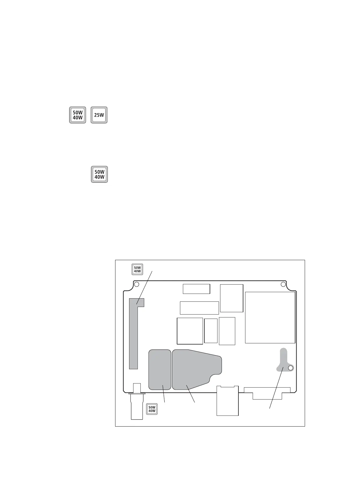
Figure 5.6 Contact surfaces on the bottom side of the main board
tin-plated
copper plate
contact surface
of rectangular
gap pad
Audio-PA area
contact surface of L-shaped gap pad
 Loading...


