418 Fault Finding of Control Head with Graphical Display TM8100/TM8200 Service Manual
© Tait Electronics Limited June 2006
14.8 On/Off Key Faulty
When battery power (13.8V) is applied to the radio, a press of the ON/OFF key
will create an active low signal (
CH ON OFF) back to the radio body to initiate
the power-on or power-off sequence. This key-press will also be detected
by the FPGA of the control head through Q611 as an active high signal
(
POWERONOFF3V3). For more information on the start-up process, refer to
“Software Architecture” on page 47.
If the
ON/OFF key is faulty:
1. Use isopropyl alcohol and a soft lens-cleaning cloth to clean the pads
S610 on the control-head board for the
ON/OFF key.
2. Check the
CH ON OFF signal level from the radio at pin 9 of the control-
head connector J103.
If the signal is approx. 13V, continue with Step 5.
If near or at ground, continue with Step 3.
3. Visually inspect pin 9 of connector J103 for open or shorted contacts.
4. Verify the source of the signal to pin 9 of connector J103 from the
radio (without the control-head connector).
5. Visually inspect R610, R606, and R624 for short-circuit to adjacent
components. Replace if necessary. Return to Step 2.
6. Visually inspect R610 for shorted or open circuits. Repair if
necessary. Retest switch.
7. Verify continuity between R610 and switch S610, and continuity
between switch S610 and ground.
If the continuity cannot be restored, replace the control-head board.
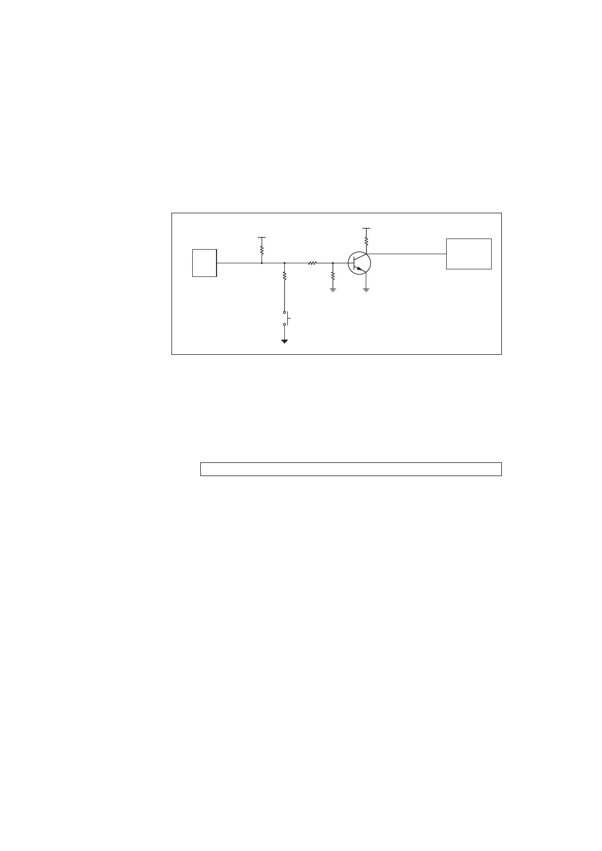
Figure 14.9 Circuit diagram of the ON/OFF key
J103 pin 9: 13V
J103
9
CH ON OFF
Control-Head
Connector
13V8
S610
1
2
3V3
POWER ON OFF 3V3
FPGA
Power
On/Off
R626
R627R610
R606
R628
Q611
 Loading...


