552 TMAA10-01 Desktop Microphone TM8100/TM8200 Service Manual
© Tait Electronics Limited June 2006
3. Squeeze the grommet and push the remaining corners into position.
4. Check that the grommet is seated correctly in the cavity.
29.3 Adjustment
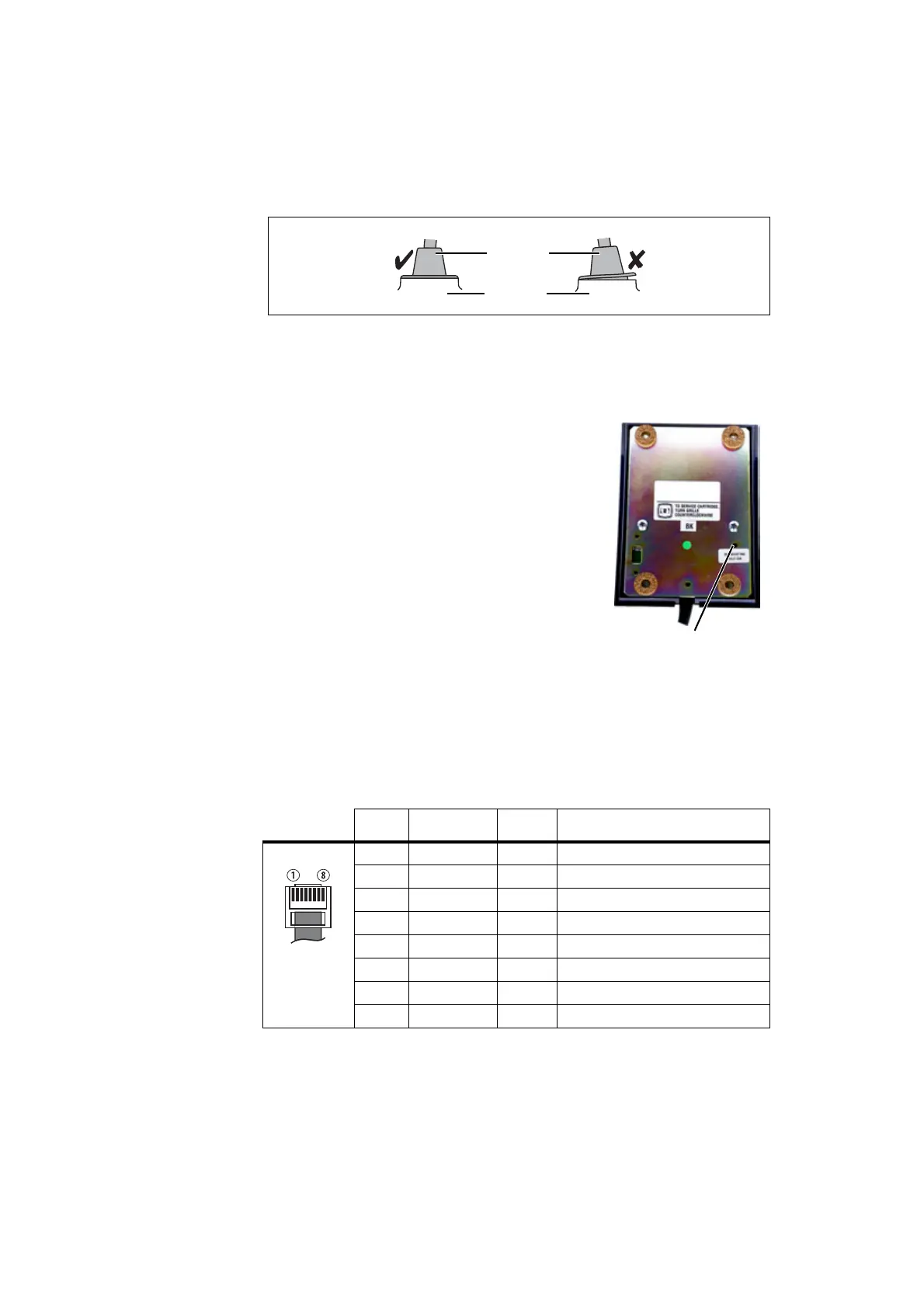
Adjust the output sensitivity of the desktop
microphone using R5. R5 is accessible from the
underside of the desktop microphone, as shown.
The microphone sensitivity is set to maximum by
rotating R5 counterclockwise.
29.4 Interface Specification
The following table and diagram summarizes the signals used for the desktop
microphone on the radio’s microphone connector and shows the interface
between the desktop microphone and the radio.
Figure 29.1 Correct desktop microphone grommet seating
microphone
grommet
control head
adjust R5 here
Table 29.1 Desktop microphone connector—pins and signals
Pin Signal Colour Description
1 — — not connected
2 — — not connected
3 — — not connected
4 MIC_PTT yellow PTT
5 MIC_AUD red audio from the microphone
6 AGND bare analogue ground
7 — — not connected
8 — — not connected
 Loading...


