TM8100/TM8200 Service Manual TMAA01-01 Line-Interface Board 459
© Tait Electronics Limited June 2006
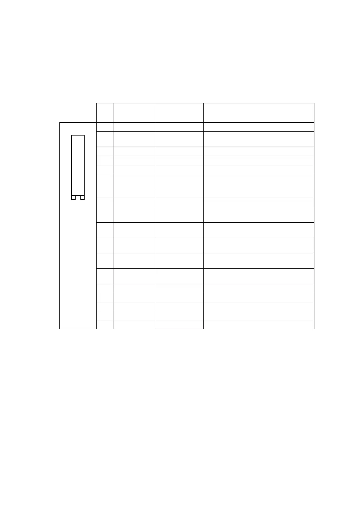
17.5 Interface Specification
The following tables summarize the signals used for the line-interface board
on the internal options connector (SK2 on the line-interface board) and the
external options connector (SK1 on the line-interface board).
Table 17.7 Internal options connector (SK2) — pins and signals
Pin Radio Signal
Line-Interface
Signal
Description
1 13V8_SW
13V8 FROM RADIO
switched 13V8 supply from the radio
2 AUD_TAP_OUT AUDIO TAP OUT
Programmable tap point out of the receive or
transmit audio chain.
3AGND AGND
analogue ground
4 AUX_MIC_AUD —
not connected
5 RX_BEEP_IN —
not connected
6 AUD_TAP_IN AUD_TAP_IN
Programmable tap point into the receive or
transmit audio chain.
7 RX_AUD —
not connected
8RSSI —
not connected
9 IOP_GPIO1 PTT FROM OPT
IOP_GPIO1 from the radio
3V3 logic level, 5V tolerant
10 IOP_GPIO2 SECONDARY BUSY
IOP_GPIO2 from the radio
3V3 logic level, 5V tolerant
11 IOP_GPIO3 BUSY
IOP_GPIO3 from the radio
3V3 logic level, 5V tolerant
12 IOP_GPIO4 AUX
IOP_GPIO4 from the radio
3V3 logic level, 5V tolerant
13 IOP_GPIO5 GPIO5
IOP_GPIO5 from the radio
3V3 logic level, 5V tolerant
14 IOP_GPIO6 —
not connected
15 IOP_GPIO7 —
not connected
16
DGND
AGND
analogue ground
17
IOP_RXD
RXD
asynchronous serial port - receive data
18
IOP_TXD
TXD
asynchronous serial port - transmit data
B
D
F
H
J
1!
1#
1%
1&
C
E
G
I
1)
1@
1$
1^
1*
top view
 Loading...


