TM8100/TM8200 Service Manual Transmitter Fault Finding (25W) 361
© Tait Electronics Limited June 2006
12.4 RF Signal Path
Introduction The RF signal path extends from the output of the frequency synthesizer to
the LPF. This section of circuitry will require investigation either following
certain checks in “Transmitter RF Power” or if the biasing checks of
“Biasing of PA Driver and PAs” reveal no fault. The procedure is divided
into nine tasks grouped as follows:
■ Task 25 to Task 28: initial RF signal path
■ Task 29 and Task 30: directional coupler
■ Task 31 and Task 32: PIN switch
■ Task 33: LPF
The initial signal path includes the exciter and PA driver. The directional
coupler, PIN switch, and LPF make up the final signal path.
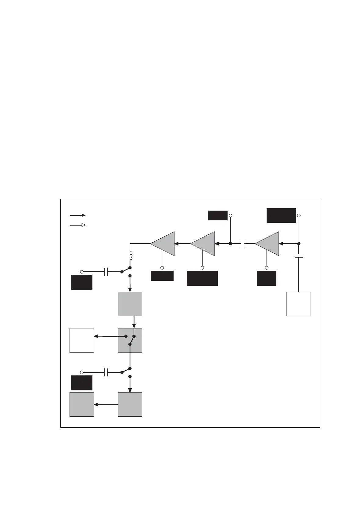
The measurement points for diagnosing faults in the signal path are
summarized in Figure 12.13.
Figure 12.13 Measurement points for diagnosing faults in the RF signal path
TEST
CAPACITOR
TEST
CAPACITOR
L314
RF CON-
NECTOR
RECEIVER
LPF
DIREC-
TIONAL
COUPLER
PAs
PIN
SWITCH
DRIVER EXCITER
FRE-
QUENCY
SYNTHE-
SIZER
SIGNALTYPES
RF
ANALOG
SYNTHESIZER
OUTPUT
SYN TX LO
PA DRIVER
OUTPUT AT
DRAIN OF Q306
BUFFER
OUTPUT
AT C313
50 TEST
LEAD TO
TEST SET
50 TEST
LEAD TO
TEST SET
EXCITER
OUTPUT
GATES OF
Q309, Q310
C301
C300
 Loading...


