TM8100/TM8200 Service Manual TMAA01-01 Line-Interface Board 451
© Tait Electronics Limited June 2006
17 TMAA01-01 Line-Interface Board
Note These instructions refer to line-interface PCB issue 220-65202-02
or later. On earlier issue PCBs, SK1 pin 5 is ground.
The TMAA01-01 line-interface board provides both audio and
digital interfaces for a variety of systems. The interfaces available are:
■ an isolated 600Ω audio interface which is capable of both
simplex operation on a two-wire system, or duplex operation on
a four-wire system
■ a keying interface which allows for two-wire keying or single
line bi-directional keying
■ a variable delay timer
■ a logic sense control.
The line-interface board fits inside the radio in the options cavity
and is connected to the main PCB by the internal options loom.
The high-density 15-way D-range connector mounted on the line-
interface board fits through the external options connector hole
provided in the radio chassis.
17.1 Operation
One of the control head function keys may be programmed to toggle the
line-interface board on and off. When the function key LED is glowing,
the line-interface board is on and when the LED is off, the line-interface
board is off.
Refer to “Programming Information” on page 458 for information on the
radio programming procedure.
17.2 Configuring the Line-Interface Board
Important This equipment contains devices which are susceptible to
damage from static charges. Refer to “ESD Precautions”
on page 108 for more information.
Important This kit does not meet the IP54 protec-
tion standard. Care must be taken when a
radio with a TMAA01-01 line-interface
board kit installed is being operated in an
environment where there is water, dust or
other environmental hazards.
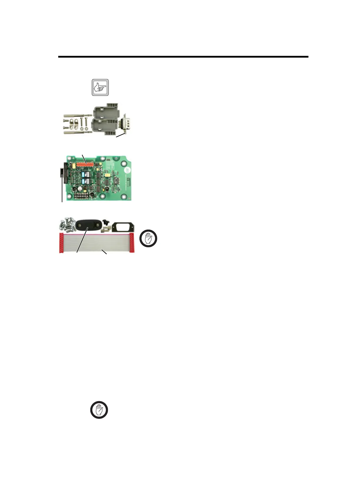
external options
connector
internal options
connector
D-range
hood parts
D-range plug
line-interface boar
line-interface
installation parts
internal options
loom
external options
cover seal
 Loading...


