452 TMAA01-01 Line-Interface Board TM8100/TM8200 Service Manual
© Tait Electronics Limited June 2006
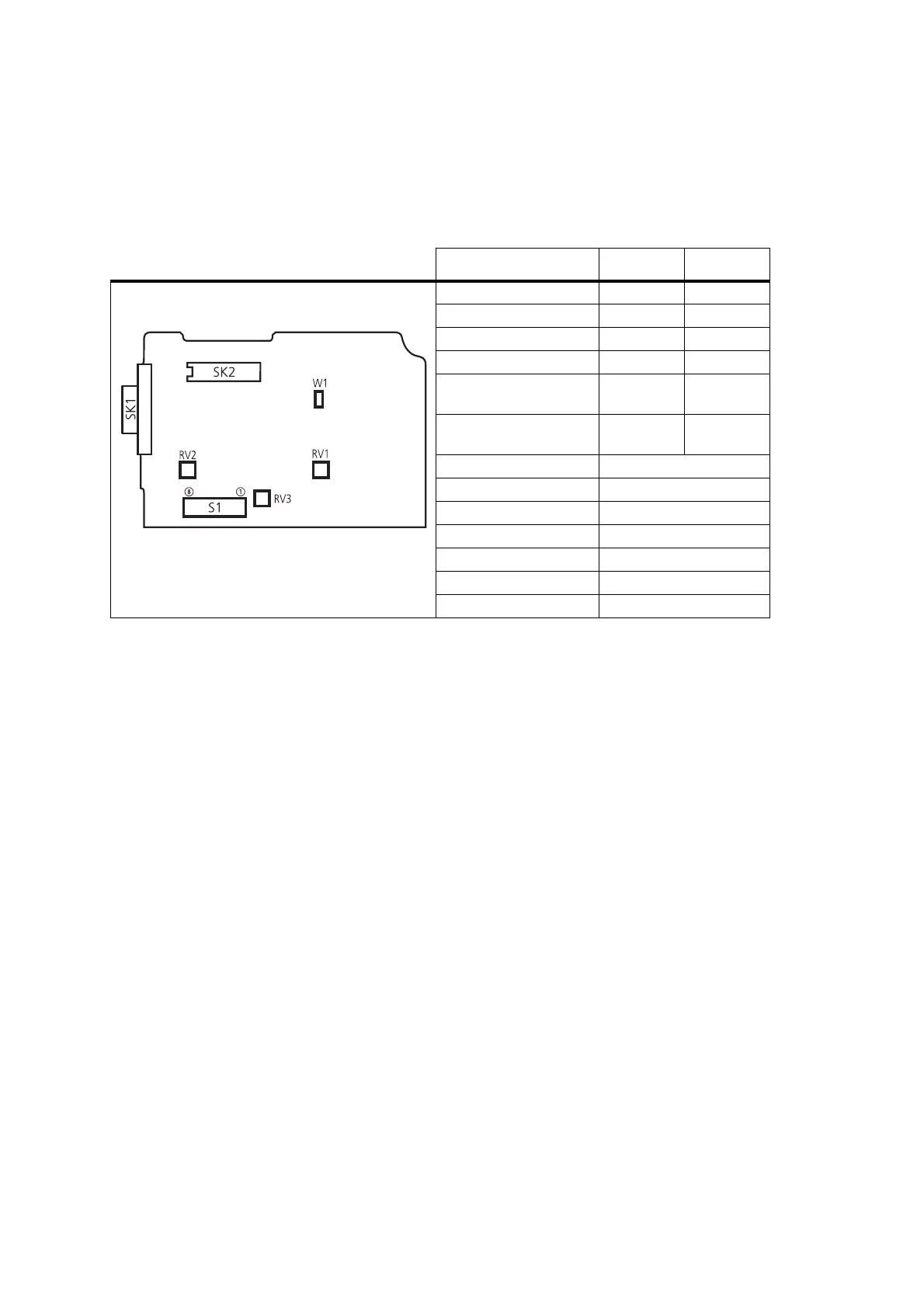
17.2.1 Adjustment Points on the Line-Interface Board
The following table describes the line-interface adjustment points.
Adjustments are made by setting the DIP switches on S1 to either “on” or
“off ” and by three variable resistors (RV1, RV2 and RV3).
17.2.2 Test Equipment Setup
The following diagram shows the setup of the test equipment used when
a d j u s t i n g RV 1 , RV 2 a n d RV 3 .
Table 17.1 Line-interface board adjustment points
Function Selection 1 Selection 2
two-wire audio interface DIP1 on DIP2 off
four-wire audio interface DIP1 off DIP2 on
busy/gate = busy DIP3 on DIP4 off
busy/gate = rx-gate DIP3 off DIP4 on
busy/gate logic
(active high)
DIP5 on DIP6 off
busy/gate logic
(active low)
DIP5 off DIP6 on
bi-directional keying line DIP7 on
two-wire keying DIP 7 off
enable gate/keying delay DIP8 on
gate/keying delay adjust RV1
audio line out level adjust RV2
audio line in level adjust RV3
time delay range W1 open
line-interface board
top side
 Loading...


