262 Transmitter Fault Finding (40W/50W) TM8100/TM8200 Service Manual
© Tait Electronics Limited June 2006
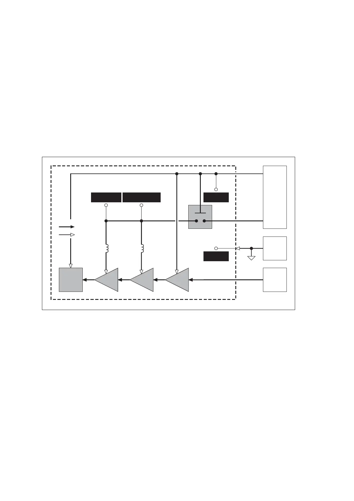
11.1 Power Supplies
Introduction First check that a power supply is not the cause of the fault. There are two
power supplies and a switch circuit for the transmitter:
■ Task 1: 13.8V DC supply from power connector (+13V8 BATT)
■ Task 2: switch circuit for 13.8V DC supply
■ Task 3: 9V DC supply from 9V regulator in PSU module (+9V0 TX).
The measurement and test points for diagnosing faults in the power supplies
are summarized in Figure 11.1.
Figure 11.1 Measurement and test points for diagnosing faults involving the power supplies for
the transmitter
GND
TEST POINT
9V0 TX
TEST POINT
SIGNALTYPES
RF
ANALOG
EXCITER
PAs
FRE-
QUENCY
SYNTHE-
SIZER
OTHER
TRANS-
MITTER
CIRCUITRY
TRANSMITTER
INTERFACE
CIRCUITRY
DRIVER
+13.8 V DC SUPPLY
TO PA DRIVER
+13.8 V DC SUPPLY
TO
PA DRIVER
+13.8 V DC
SUPPLY TO PAs
L310
POWER
SUPPLY
AGND
+9V0 TX
+13V8 BATT
SWITCH
L306
 Loading...


