534 Installing an Enhanced Remote Kit TM8100/TM8200 Service Manual
© Tait Electronics Limited June 2006
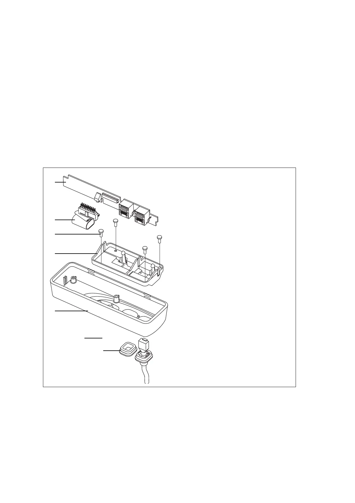
26.3 Servicing the Remote Control-Head Installation Parts
26.3.1 Disassembling the Torso Interface
Disassemble only as much as is necessary to replace the defective parts.
Re-assembly is carried out in reverse order of disassembly.
1. Release the clip of the PCB bracket
E and remove the control-
head board
B.
2. Disconnect the torso-interface loom
C.
3. Unscrew the four PT type screws
D and remove the PCB bracket E.
Figure 26.4 Parts of the torso interface
Description IPN
B control-head board
C torso-interface loom 219-02882-XX
a
D 3 x 8 PT screw (x4) 346-10030-XX
a
E PCB bracket 302-10063-XX
a
F front panel 316-06843-XX
a
G label 365-01751-XX
a
H RJ45 bung 302-50002-XX
a
a
Contact Technical Support for the exact IPN.
B
D
F
x4
C
G
H
E
 Loading...


