TM8100/TM8200 Service Manual Disassembly and Reassembly 141
© Tait Electronics Limited June 2006
5.4 Disassembling and Reassembling the Control Head
5.4.1 Control Head with Graphical Display
Disassemble only as much as necessary to replace the defective parts.
Reassembly is carried out in reverse order of the disassembly.
The circled numbers in this section refer to the items in Figure 5.9 on
page 143.
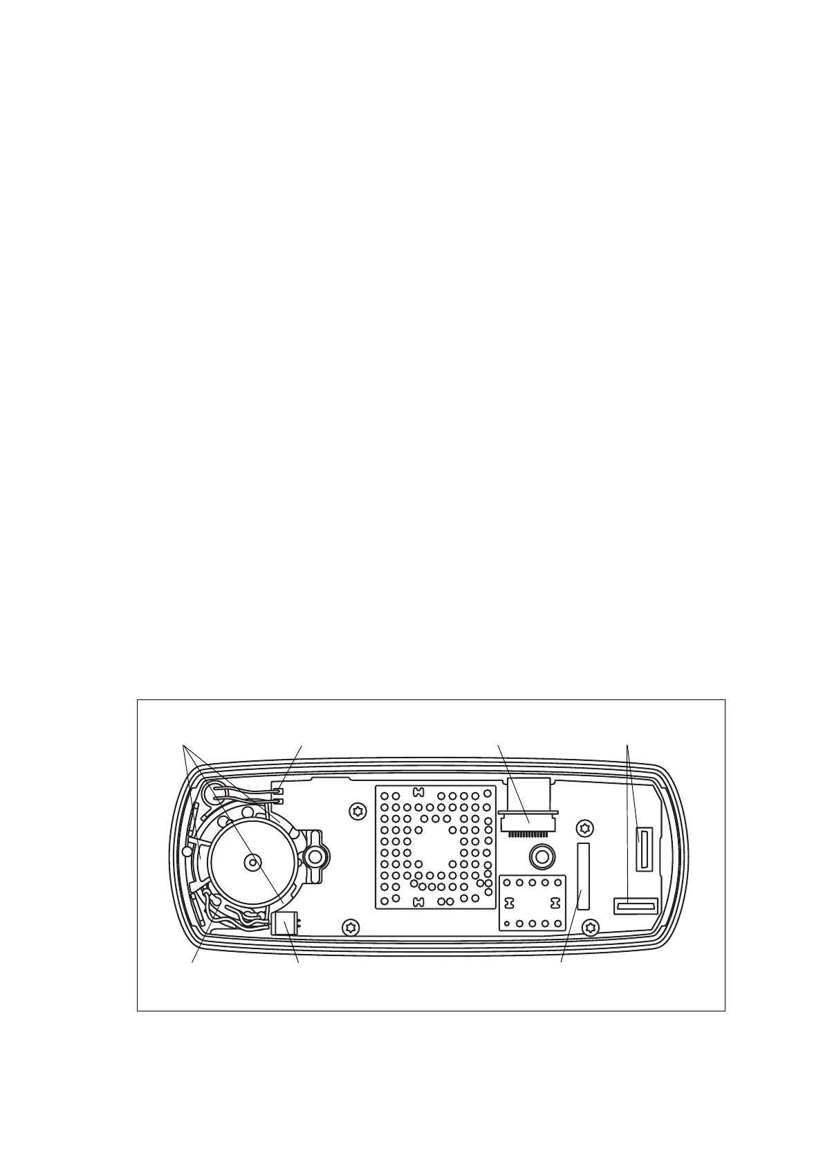
The connectors of the control-head board and the orientation of the speaker
and speaker clamp are illustrated in Figure 5.8.
1. With your fingers, pull off the volume control knob
1&.
Do not use any tools as this might cause damage.
2. Unscrew the two screws
B and remove the adaptor flange C.
3. Disconnect the control-head loom
D.
4. If an optional circuit board is fitted, unplug it from the control-head
board
F (refer to Figure 5.8).
5. Note whether the speaker is connected or disconnected. If it is
connected, disconnect the speaker cable from the speaker connector
of the control-head board
F (refer to Figure 5.8). Note that the radio
must be returned to the customer in its original configuration.
6. Release the lock of the LCD connector and unplug the loom of the
LCD assembly
1@ (refer to Figure 5.8). Note that the loom runs
through a slot in the space-frame
J.
Figure 5.8 Speaker orientation and connectors of the control-head board (graphical display)
connectors for
optional circuit board
connector for speaker
connector for
loom of LCD assembly
connector for
control-head loom
3470z_01
pads for leads of
concealed microphone
speaker terminals
legs of the
speaker clamp
 Loading...


