474 TMAA01-02 RS-232 Board TM8100/TM8200 Service Manual
© Tait Electronics Limited June 2006
18.3 Interface Specification
The following tables summarize the signals used for the RS-232 board on the
internal options connector (SK1 on the RS-232 board) and the external
options connector (SK2 on the RS-232 board).
Note The TM8000 3DK Hardware Developer’s Kit Application
Manual contains a detailed electrical specification for the signals
available on the radio’s internal options connector. This manual is
part of the 3DK Resource CD, which can be purchased using
product code TMAA30-01.
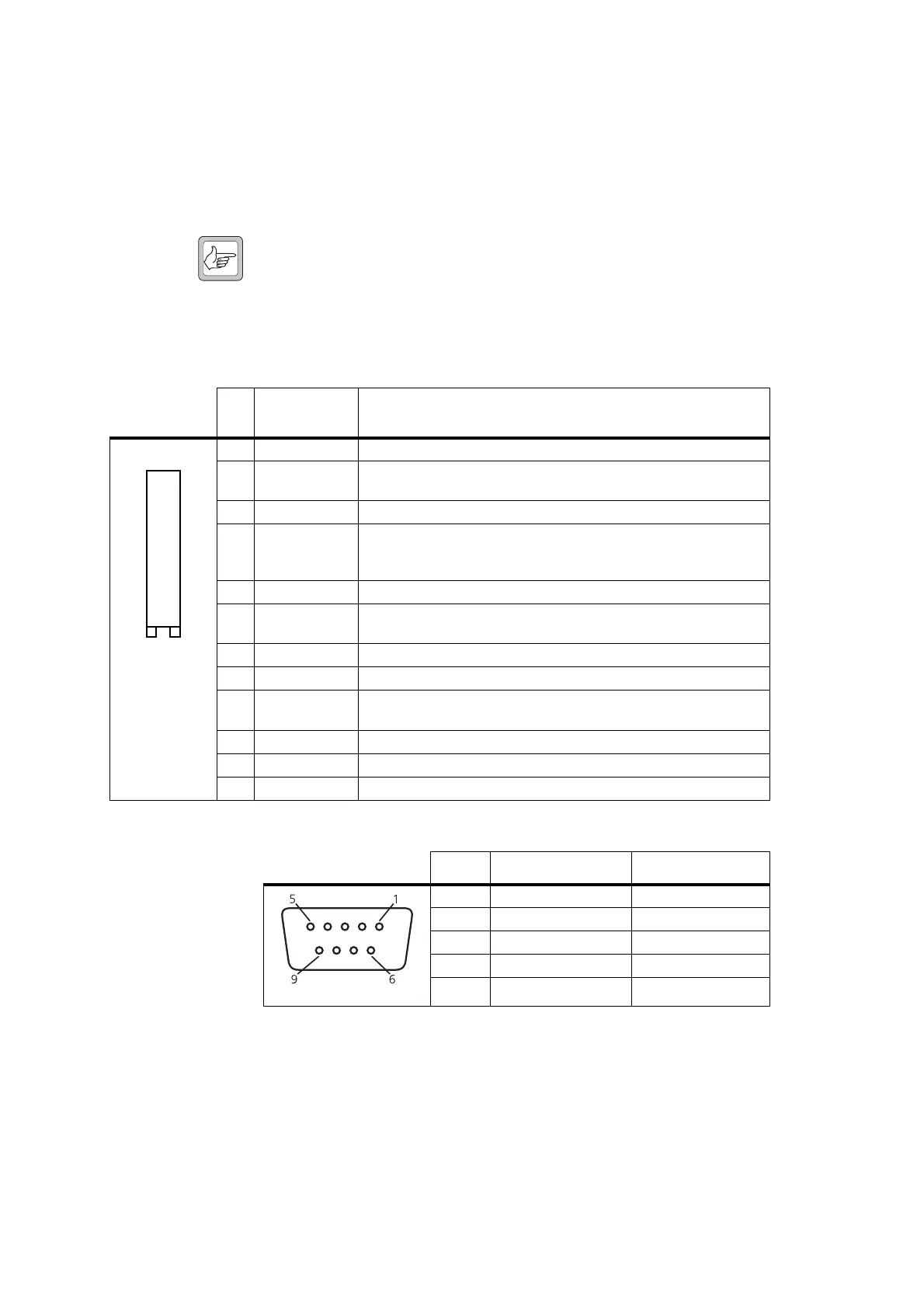
Table 18.2 Internal options connector—pins and signals
Pin
Connector
Signal
Description
1 13V8_SW
switched 13V8 supply from the radio
2 AUD_TAP_OUT
Programmable tap point out of the receive or transmit audio chain.
DC-coupled
3AGND
analogue ground
4 AUX_MIC_AUD
Auxiliary microphone input, with electret microphone biasing
provided.
Dynamic microphones are not supported.
5 RX_BEEP_IN
receive sidetone input, AC-coupled
6 AUD_TAP_IN
Programmable tap point into the receive or transmit audio chain.
DC-coupled
7 RX_AUD
not connected
8 RSSI
analogue RSSI output
9-15 IOP_GPIO1 to
IOP_GPIO7
programmable function and direction
16
DGND digital ground
17
IOP_RXD an RS-232 compliant asynchronous serial port - receive data
18
IOP_TXD an RS-232 compliant asynchronous serial port - transmit data
B
D
F
H
J
1!
1#
1%
1&
C
E
G
I
1)
1@
1$
1^
1*
top view
Table 18.3 External options connector (SK2) — pins and signals
Pin Signal Direction
2 serial transmit data
output from the radio
3 serial receive data
input to the radio
5 data ground
—
7 RTS using IOP_GPIO3
input to the radio
8 CTS using IOP_GPIO1
output from the radio
front view
 Loading...


