TM8100/TM8200 Service Manual Fault Finding of Control Head with Graphical Display 417
© Tait Electronics Limited June 2006
2. With the intensity set to high, check the signals at pins 2 (B1) and 5
(B2) of Q2.
If any of these signals are incorrect, the FPGA is faulty and the con-
trol-head board must be replaced.
3. Check the signals at pins 6 (C1) and 3 (C2) of Q2. Check the signals
at pins 1 (E1) and 4 (E2) of Q2.
If any of these signals are incorrect, Q2 is faulty.
4. Check the resistors R607, 611, and R613 for shorted or open
circuits.
Q2 pin 2 (B1): GND
Q2 pin 5 (B2): GND
Q2 pin 6 (C1): 3.3V
Q2 pin 3 (C2): 3.3V
Q2 pin 1 (E1): 3.3V
Q2 pin 4 (E2): 3.3V
R607: 3.3kΩ
R611: 2.2kΩ
R613: 1kΩ
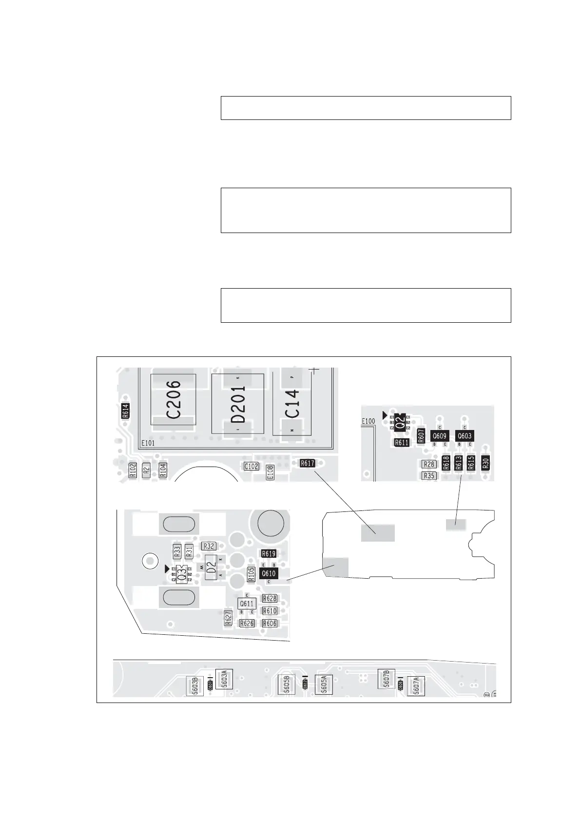
Figure 14.8 PCB layout of the keypad backlighting circuitry
top side
bottom side
top side
top side
 Loading...


