Do you have a question about the Tait TM8110 and is the answer not in the manual?
| IP Rating | IP54 |
|---|---|
| Channel Spacing | 12.5 kHz / 25 kHz |
| Modulation | FM |
| Operating Temperature | -30°C to +60°C |
| Frequency Range | 136-174 MHz, 403-470 MHz, 450-520 MHz |
Overview of the TM8100 and TM8200 series radios, covering frequency bands, RF output power, accessories, and product codes.
Details the available frequency bands for the radios, such as A4, B1, C0, D1, H5, H6, and H7.
Describes the two RF output power options available: 40W/50W and 25W.
Lists various audio accessories, installation kits, internal options boards, and other accessories for the radios.
Explains the product codes used to identify TM8100 and TM8200 mobile radio products and their features.
Discusses repair levels, website access, tools, equipment, spares, test equipment setup, and servicing precautions.
Details the manual's coverage of level-1 and level-2 repairs and outlines website access levels for technical information.
Covers essential precautions for servicing radios, including mechanical, compliance, anti-static, and transmitter issues.
Provides instructions on how to remove and mount the control head, and disassemble/reassemble the radio body and control heads.
Describes two types of initial checks: calibration checks and lock status, depending on fault symptoms.
Details the four power supplies for the frequency synthesizer and measurement points for diagnosing faults.
Explains checking critical PLL outputs and inputs, including charge pump supply and reference frequency.
Guides on checking loop filter functionality by measuring loop voltage, VCO fault, reference voltage, and feedback voltage.
Covers determining the extent of receiver sensitivity loss and checking receiver gain.
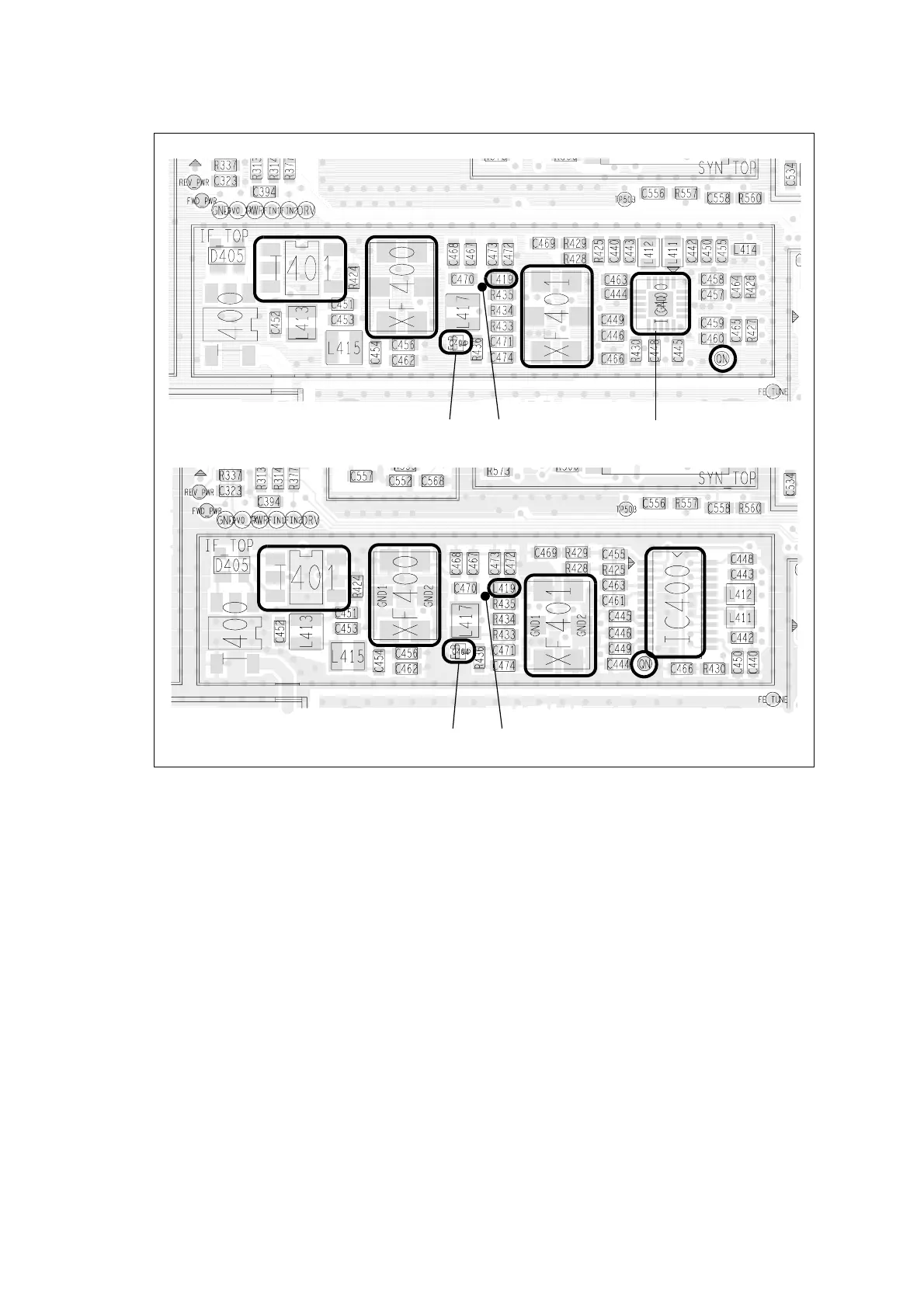
Details fault diagnosis for excessive receiver sensitivity loss, covering power supplies, logic signals, lock status, IF amplifier biasing, and matching circuitry.
Addresses issues with incorrect RSSI readings, focusing on AGC voltage calibration and RSSI delta gain.
Checks the two power supplies and the switch circuit for the transmitter, including 13.8V DC and 9V DC supplies.
Guides on checking transmitter RF power, including forward/reverse powers and output power, and troubleshooting based on results.
Details checking and repairing biasing for Power Amplifiers (PAs) and the PA driver, including DAC values and current readings.
Checks the 9V, 3V, and 2.5V DC supplies for the CODEC and audio circuitry.
Covers diagnosing faults related to no speaker audio or distorted speaker audio, checking audio power amplifier and speaker outputs.
Addresses issues where the receiver does not operate, checking level shifter and QN test point.
Lists CCTM commands used for fault finding of the control head, including LED, LCD, and key functions.
Guides on checking 3.3V and 13.8V supply voltages to the control head and its components.
Provides steps for troubleshooting a faulty LCD display, including checking connections, contacts, and replacing the LCD.
Covers troubleshooting LCD backlighting issues, including checking supply voltage, signals, and components like Q102.
Focuses on diagnosing faults where the display functions partially or not at all, checking elastomeric strips and LCD.
Outlines procedures for when all LEDs are faulty, including checking IC3 and replacing the control-head board.
Details troubleshooting steps for individual or groups of faulty keys on the control head.
Lists serviceable parts for the radio body, including cover, lid, chassis, and connectors, with IPNs and quantities.
Lists serviceable parts for the graphical display control head, including screws, loom, keypad, and LCD assembly.
Lists serviceable parts for control heads with 1-, 2-, or 3-digit displays, such as looms, keypads, and LCDs.
Explains the operation of the line-interface board, how to toggle it on/off with function keys, and radio programming.
Provides a step-by-step procedure for installing the line-interface board, including parts required and tightening torques.
Summarizes signals for the options-extender board on internal and external connectors, including pinouts and descriptions.
Details the circuit description for the audio and logic interfaces of the line-interface board.