Compensating a passive voltage probe
Probe compensation adjusts a passive (nonamplified) voltage probe for the most
accurate high-frequency response. The oscilloscope has a 1 kHz square wave
source for compensating the probe. Because a square wave contains a significant
number of harmonics (multiples of the fundamental frequency), it is an ideal
signal source for adjusting the high frequency response of a probe.
A rounded leading edge on the square wave means that the high frequency
response of the probe is too low. A spike on the leading edge means that the high
frequency response is too high and must be reduced. A square leading edge
means that the frequency response is correct for the probe.
Whenever you attach a passive voltage probe for the first time to any input
channel, or change a passive probe from one channel to another, you must
compensate the probe to match it to that input channel.
To properly compensate your passive probe:
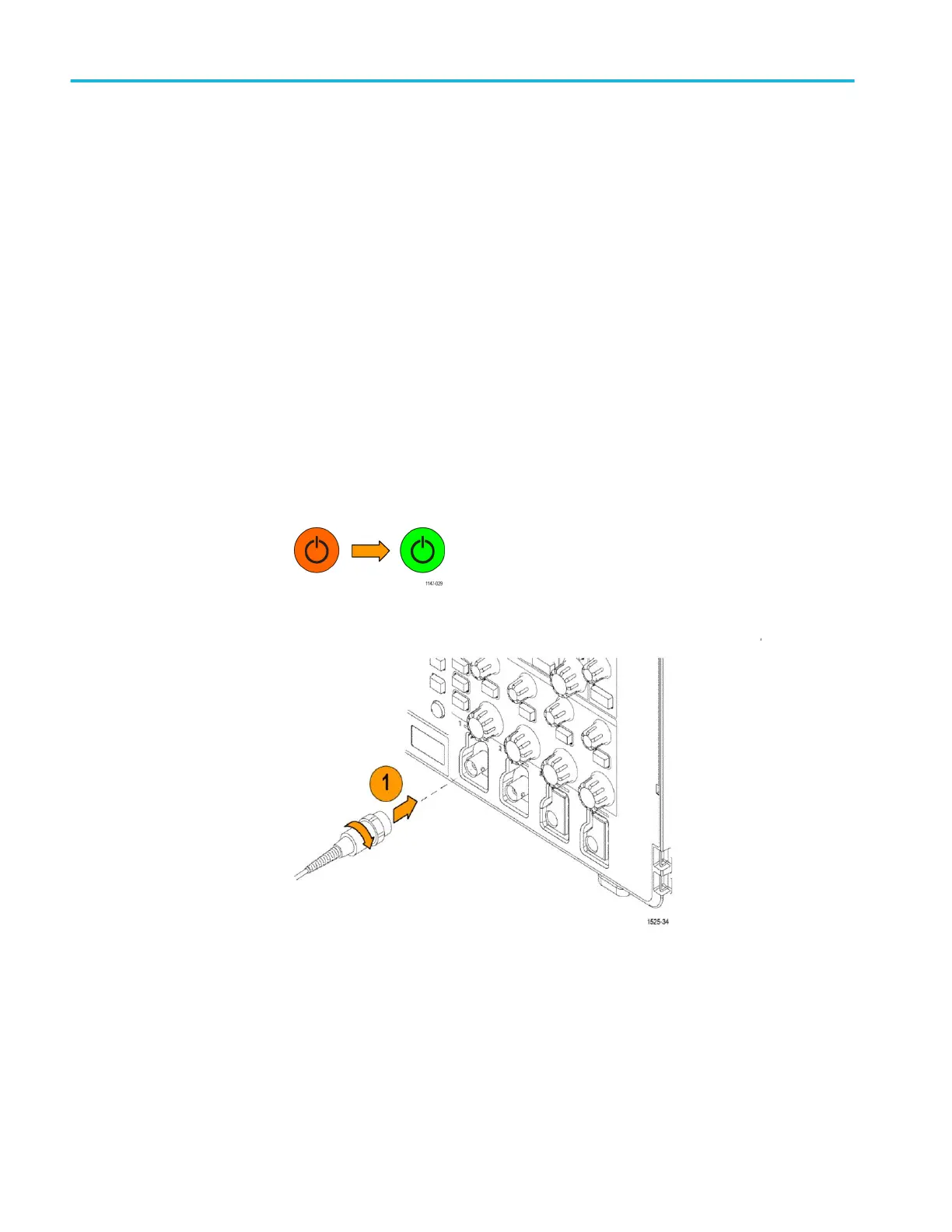
1. Power on the oscilloscope.
2. Connect the probe to an oscilloscope channel.
Getting acquainted with the oscilloscope
28 TBS2000B Series Oscilloscopes User Manual
 Loading...


