Getting Acquain
ted With Your Instrument
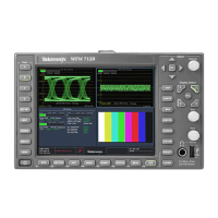
AES A/B Connectors
1. These BNC connectors support AES
audio inputs.
A1-2 In
A3-4 In
A5-6 In
A7-8 In
B1-2 I/O
1
B3-4 I/O
1
B5-6 I/O
1
B7-8 I/O
1
Options DS, AD, DDE
1
The AES B connectors can be configured to output embedded audio channels, decoded Dolby, or the AES A inputs.
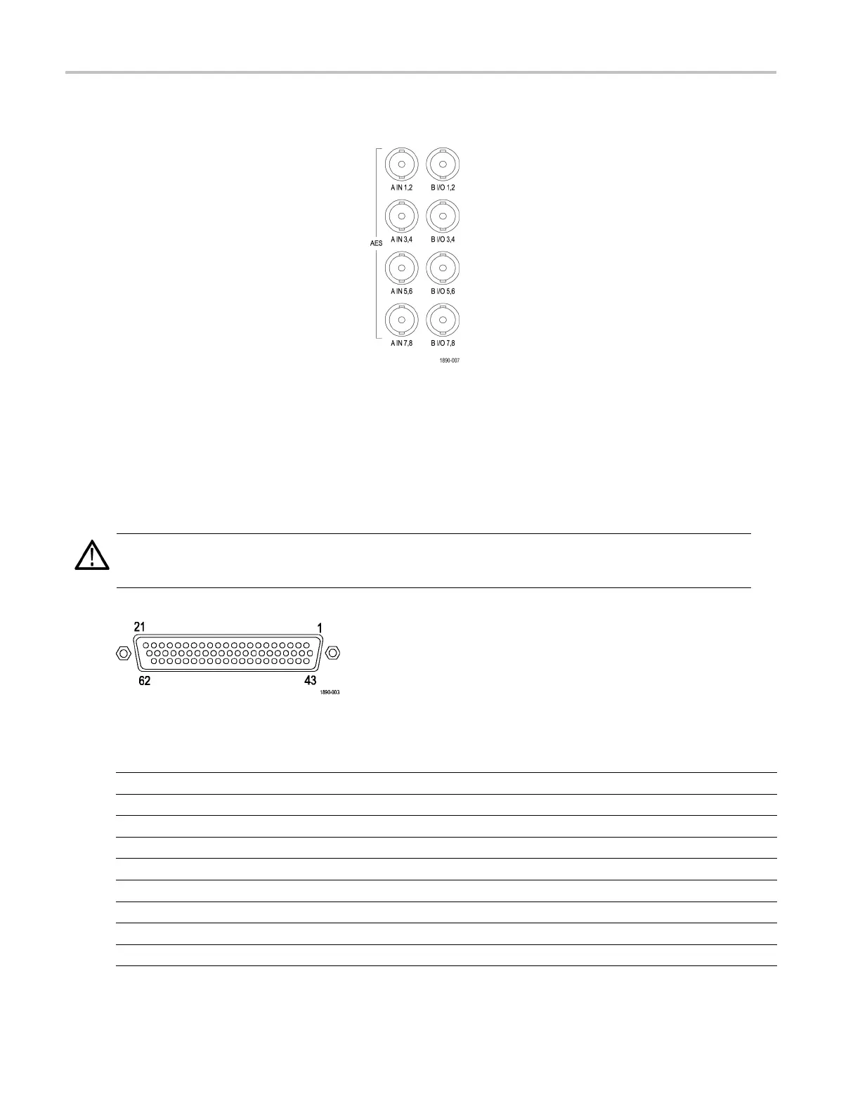
Analog Input/Output Connector
The Analog I/O connector is used to receive and send analog si gnals. The Analog I/O connector is a 62-pin, D-subminiature
connector. Pin assignments and pin names are listed in the following figure and table.
CAUTION. Use care when connecting the Analog Audio Output. Refer to the instrument Specifications to ensure that the
Audio Load and Output Power meet specifications. Exceeding Analog Audio Output Power may result in damage to
the instrument.
Option AD
Pin Description
1 ANALOG_INPUT_A1_P Balanced differential analog audio input- Ch. 1, line A, positive.
2 ANALOG_INPUT_B1_P Balanced differential analog audio input- Ch. 1, line B, positive.
3 ANALOG_INPUT_A2_P Balanced differential analog audio input- Ch. 2, line A, positive.
4 ANALOG_INPUT_B2_P Balanced differential analog audio input- Ch. 2, line B, positive.
5 ANALOG_INPUT_A3_P Balanced differential analog audio input- Ch. 3, line A, positive.
6 ANALOG_INPUT_B3_P Balanced differential analog audio input- Ch. 3, line B, positive.
7 ANALOG_INPUT_A4_P Balanced differential analog audio input- Ch. 4, line A, positive.
8 ANALOG_INPUT_B4_P Balanced differential analog audio input- Ch. 4, line B, positive.
9 ANALOG_INPUT_A5_P Balanced differential analog audio input- Ch. 5, line A, positive.
14 Waveform Monitors Quick Start User Manual
 Loading...