ELECTRICAL
5-6 Rev. 000 TX525 Service Manual
Engine Oil Pressure and Battery
Charge Indicator Light Cluster
Testing
Purpose
1. Disconnect the relay from the harness.
2. Verify the coil resistance between terminals 85 and
86 with a multimeter (ohms setting). Resistance
should be from 70 to 90 ohms. There should be
continuity between terminals 87a and 30 (Fig. 0807).
The engine oil pressure indicator light noties the oper
ator that the engine oil pressure is too low.
The battery charge indicator light noties the operator
that the battery charge has become too low.
Fig 0807 xl relay
3. Connect the multimeter (ohms setting) leads to relay
terminals 30 and 87. Ground terminal 86 and apply
+12 VDC to terminal 85. The relay should make and
break continuity between terminals 30 and 87 as 12
VDC is applied and removed from terminal 85 (Fig.
0000 above).
4. Connect the multimeter (ohms setting) leads to relay
terminals 30 and 87a. Apply +12 VDC to terminal
85. With terminal 86 still grounded, the relay should
break and make continuity between terminals 30
and 87a as 12 VDC is applied and removed from the
terminal (Fig. 0000 above).
5. Disconnect voltage and multimeter leads from relay
terminals.
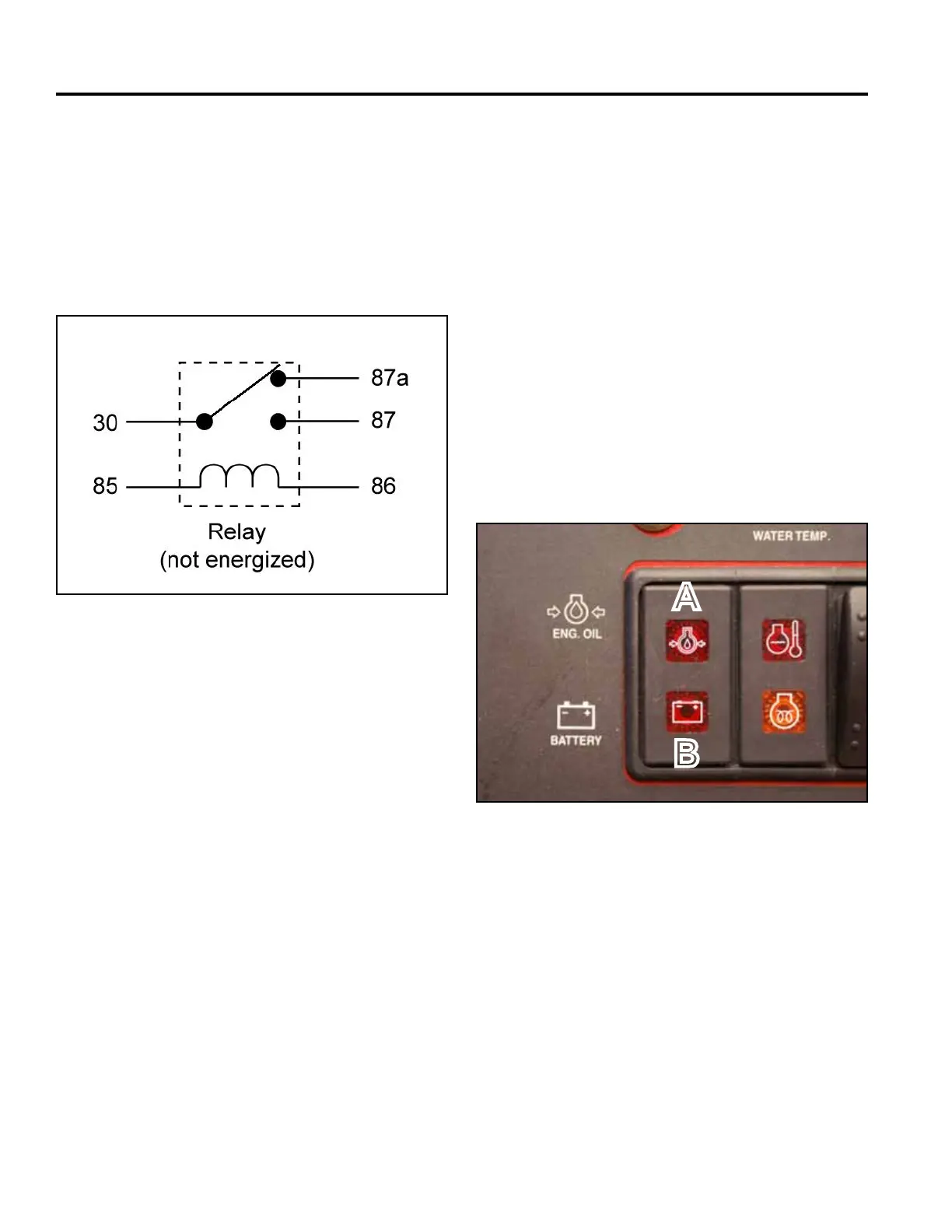
Location
The Engine Oil Pressure/Battery Charge Indicator light
cluster is located in the center of the control panel (Fig.
0808).
Fig 0808 PICT-5282
A. Engine Oil Pressure Light
B. Battery Charge Indicator Light
A
B