HYDRAULIC SYSTEM
6-14 Rev. 000 TX525 Service Manual
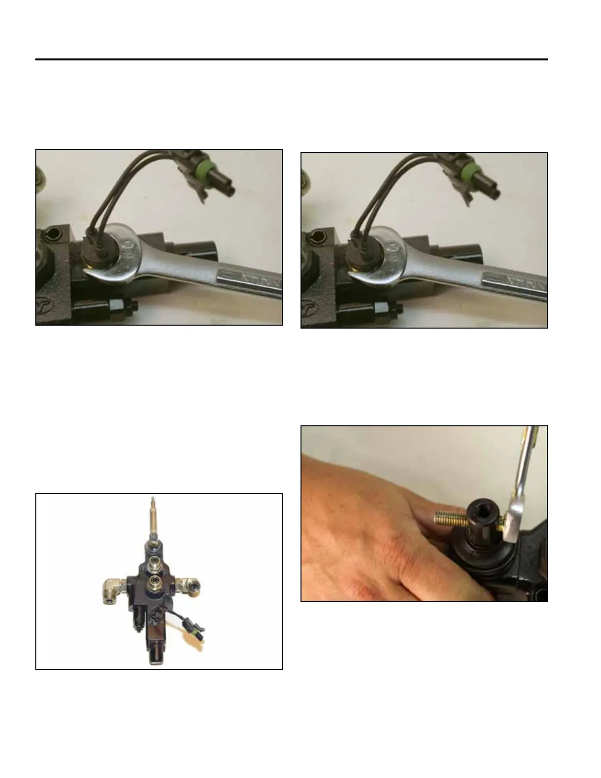
21. Using a 7/8” wrench, remove the switch from valve
(Fig. 0881).
Note: Replace o-ring on the switch.
Fig 0881 PICT-1780a
22. If the valve is to be rebuilt, refer to “Auxiliary Valve
Rebuild” on page 6-57.
23. If a new valve is being installed, transfer all ttings
and markings to the new valve (Fig. 0882).
Note: Replaceallo-ringsonthettingspriorto
installing into the replacement valve.
Fig 0882 CLR DSC-3653
Auxiliary Valve Installation
1. Using a 7/8” wrench, install the switch into the valve
(Fig. 0883).
Fig 0883 PICT-1780a
2. Use a 1/2” wrench, thread the spacer mounting bolt
into the valve cap (Fig. 0884).
Fig 0884 PICT-1778

 Loading...


