ELECTRICAL
5-13TX525 Service Manual Rev. 000
Alarm, Low Engine Oil
Purpose
Location
Testing
The audio alarm is located in the control panel under the
left control panel cover (Fig. 0821).
Disconnect the two wires and remove the mounting
screws. Remove the sender from the fuel tank. Place
the VOM negative lead on the negative terminal and the
positive lead on the center stud. Refer to the chart below
for proper resistance depending on oat position.
Float Position Resistance
Full 33 ohms + 20 ohms
Empty
240 ohms + 6 ohms
Fig 0821 IMG-6937
The audible alarm produces a pulsating loud tone to
alert the operator of high engine temperature.
How It Works
Testing
There is +12VDC applied to the audio alarm when the
key is in the ON or RUN positions. The Water Temper-
ature Light provides a ground for the light and the audio
alarm.
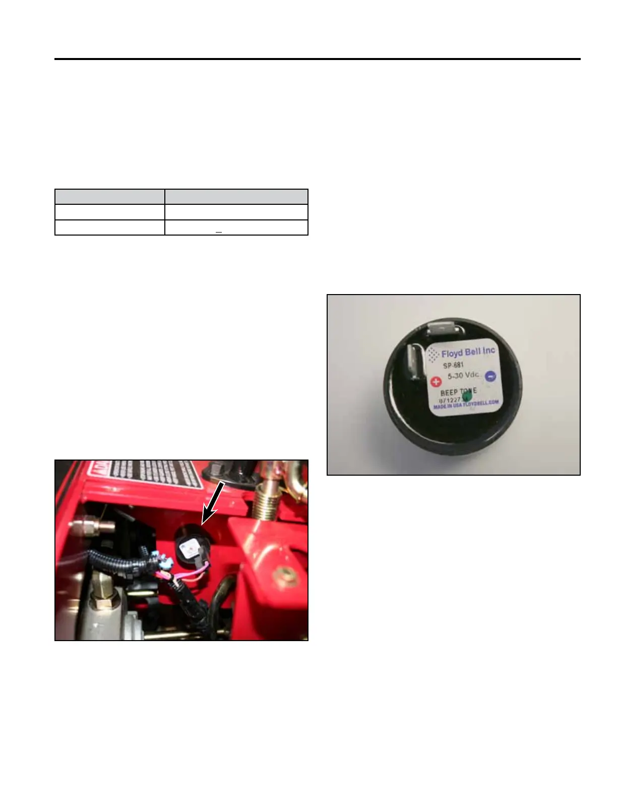
Ground the negative terminal (-) on the alarm. Apply
12 volts to the positive terminal (+) on the alarm. If the
alarm does not sound, replace the alarm. If the alarm
does sound test the electrical circuit (Fig. 0822).
Fig 0822 IMG-6969a

 Loading...


