HYDRAULIC SYSTEM
6-51TX525 Service Manual Rev. 000
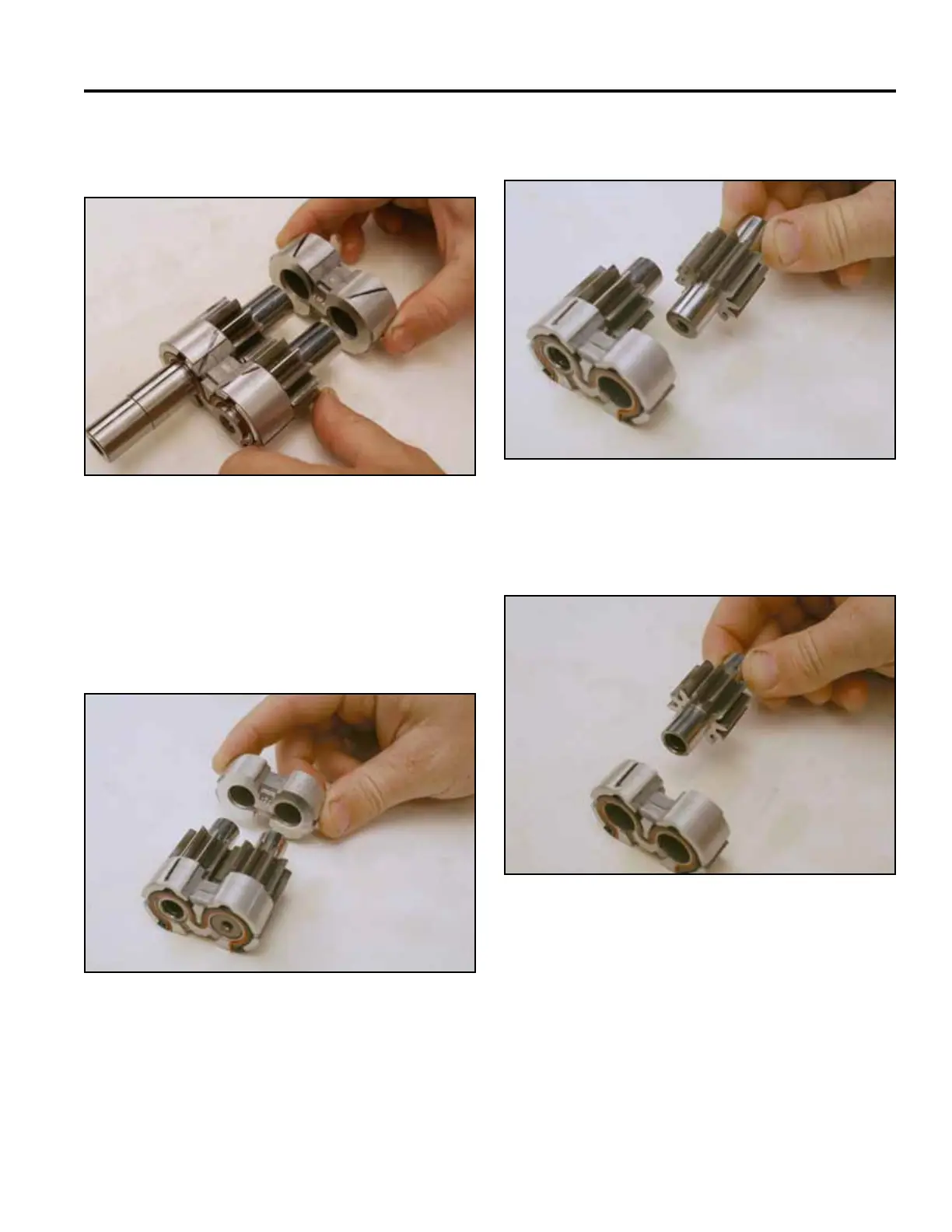
6 gpm Pump Assembly
13. Install the second bushing onto the 2 gears (Fig.
1022).
2. Remove the driven gear (Fig. 1024).
Fig 1022 PICT-2865a
Fig 1024 PICT-2867a
3. Remove the drive gear (Fig. 1025).
Note: Lubricate all surfaces on reassembly.
1. Remove one of the bushings (Fig. 1023).
Fig 1025 PICT-2868a
Fig 1023 PICT-2866a

 Loading...


