ELECTRICAL
5-12 Rev. 000 TX525 Service Manual
How It Works
A oat is attached to a pivoting lever. The pivoting lever
rotates a potentiometer (a device similar to the volume
control on a stereo) to vary resistance. The resistance
should vary from 33 to 240 ohms.
Fuel Sender
Purpose
Location
This electrical component sends a varying voltage to the
control panel gauge corresponding to the fuel level in the
tank.
The fuel sender is mounted on the right side of the top
surface of the fuel tank (Fig. 0820).
Fig 0820 PICT-5607
Testing
1. Before electrically testing the switch, check the loc-
ation of the switch and bolt, to make sure they are
meeting in the sense zone on the switch. Both the
switch and the bolt are adjustable and the air gap
between them should be 1/8” to 1/4” (3.2 to 6.4mm).
2. Disconnect the switch from the wiring harness and
remove it from the unit.
3. Using a multimeter (ohms setting), check the con-
tinuity of the switch at the wire terminals. There
should be NO continuity (switch open).
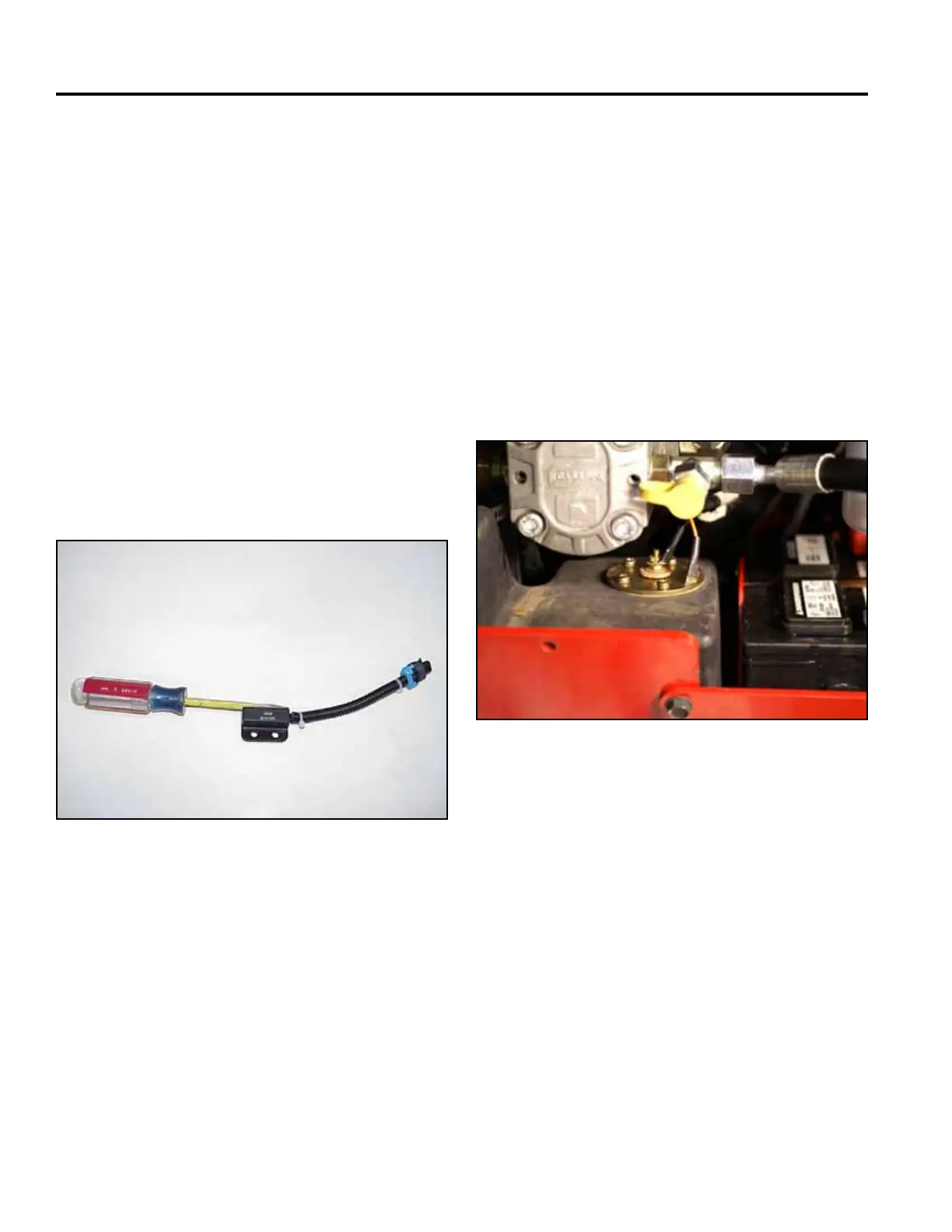
4. Using the steel blade of a screw driver (a stainless
steel blade will not activate swtich), or similar object,
touch the blade of the screw driver against the
sense zone of the switch. There should be continuity
(switch closed) (Fig. 0819).
Fig 0819 CLR MVC-879X

 Loading...


