HYDRAULIC SYSTEM
6-74 Rev. 000 TX525 Service Manual
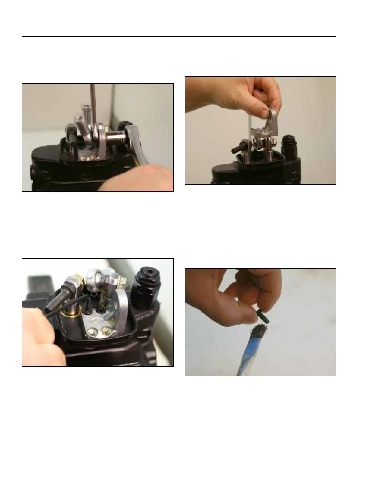
7. Using a 13mm socket and wrench, remove the nut
holding the joystick joint and then remove the pivot
for the lift and tilt operation (Fig. 1111).
9. Remove the joystick pivot from the valve assembly
(Fig. 1113).
Fig 1111 PICT-2596a
Fig 1113 PICT-2598a
1. Apply thread locking compound on the threads
of both screws that secure the pivot to the valve
assembly (Fig. 1114).
8. Turn the loader lift joystick joint. Using a 3mm Allen
wrench, remove the 2 hex head screws securing the
joystick pivot to the valve assembly (Fig. 1112).
Fig 1114 PICT-2599a
Fig 1112 PICT-2597
Joystick Assembly Installation

 Loading...


