HYDRAULIC SYSTEM
6-73TX525 Service Manual Rev. 000
3. Using a 6mm Allen wrench, loosen the 3 hex head
screws and spring lock washers (Fig. 1107).
5. Pictured below are the joystick joints (Fig. 1109).
Fig 1107 PICT-2591a
Fig 1109 PICT-2593a
6. Slide the end rod off the pin of the joystick joint for
the tilt cylinder (Fig. 1110).
4. Remove the articulated holder, screws and washers
from the valve assembly (Fig. 1108).
Fig 1110 PICT-2601a
Fig 1108 PICT-2592a
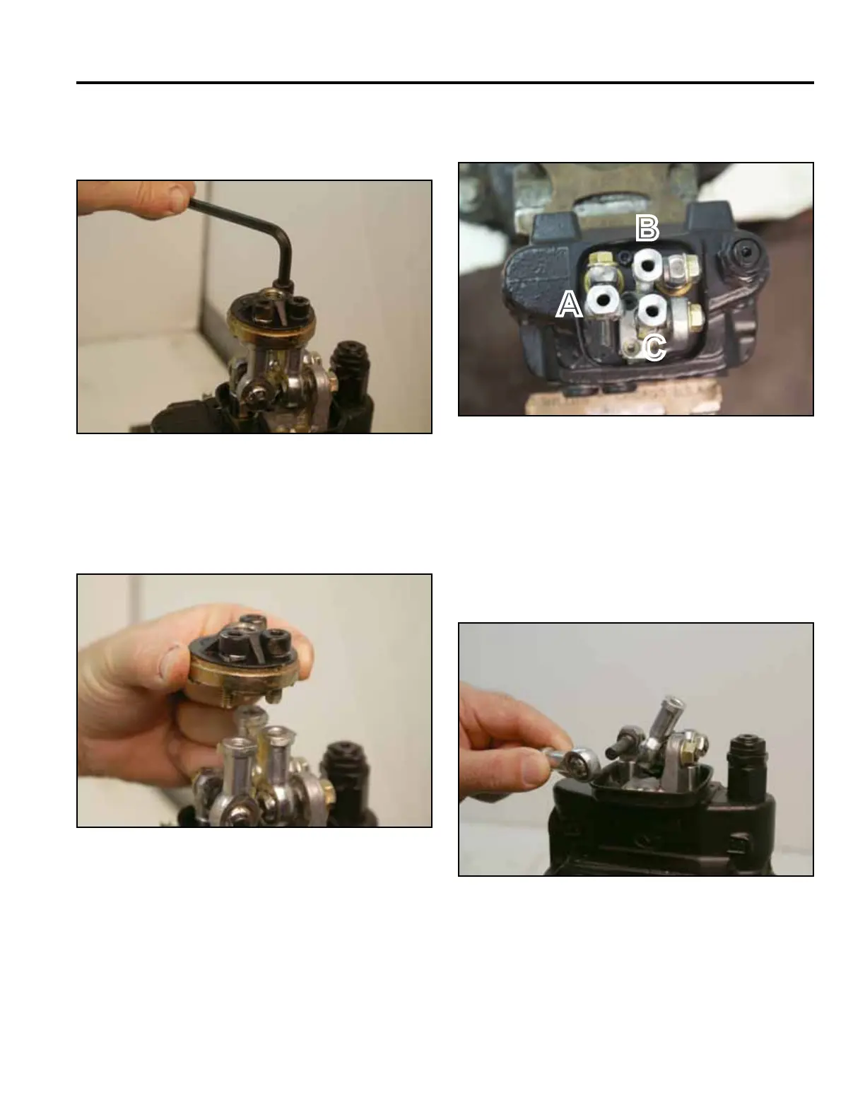
A. Tilt Cylinder operation
B. Loader Lift Cylinder operation
C. Pivot for Lift and Tilt operation
A
B
C

 Loading...


