HYDRAULIC SYSTEM
6-30 Rev. 000 TX525 Service Manual
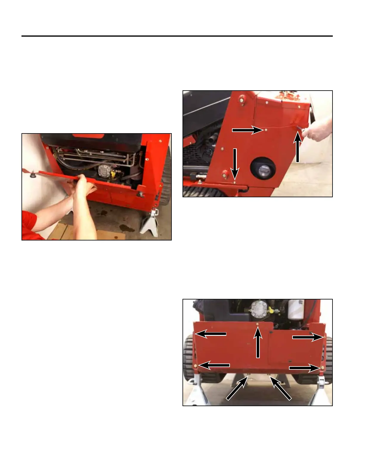
3. Using a 3/8” socket, remove the 6 screws that
secure the left and right rear cover support panels to
the tower assembly (3 screws per panel). Remove
the panels (Fig. 0943).
Fig 0943 PICT-4256
4. Using 3/4” and 1/2” sockets, remove the 7 bolts and
nuts securing the rear frame cover to the frame and
fuel tank bracket. Remove the rear frame cover (Fig.
0944).
Note: The rear of the machine may have to be lifted
to reposition the jack stands so that the rear
frame cover can be removed.
Fig 0944 PICT-4259
Hydraulic Tandem Pump
Replacement
Hydraulic Tandem Pump Removal
1. Raise the machine and set it on jack stands. Refer to
“Lifting the Machine for Service” on page 7-1.
2. Remove the rear access panel (Fig. 0942).
Fig 0942 PICT-4505