DRIVE SYSTEM
7-62 Rev. 000 TX525 Service Manual
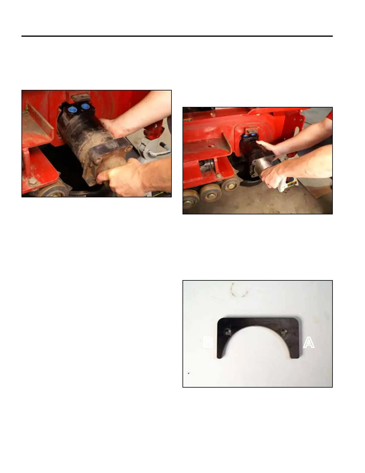
25. Rotate the wheel motor 90° so the ports are facing
upward, this will allow the raised portion of the wheel
motortotthroughthenotchintheframe.Remove
the wheel motor (Fig. 1497).
Fig 1497 PICT-4466
26. For wheel motor service, Refer to the Parker / Ross
Wheel Motor Service Manual (Toro p/n: 492-4753).
Wheel Motor Installation
1. Insert the wheel motor into the frame with the
ports facing up. After the wheel motor is inside the
frame, rotate the wheel motor 90° clockwise so the
hydraulic ports are facing to the rear (Fig. 1498).
A. Wide Side B. Narrow Side
Fig 1498 PICT-4471
2. Wheel motor mounting plates have a wide side and
narrow side. The wide side faces up when installing
the wheel motor (Fig. 1499).
Fig 1499 PICT-4473a
AB

 Loading...


