DRIVE SYSTEM
7-61TX525 Service Manual Rev. 000
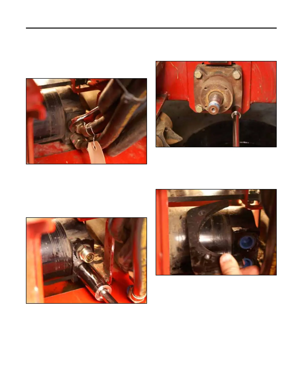
21. Place a drain pan under the wheel motor that is
being removed. Using a 1-1/8” 15°/60° offset open
end wrench, disconnect the two hydraulic lines
running to the wheel motor. Install protective caps on
the hydraulic lines (Fig. 1493).
Fig 1493 PICT-4461
22. Using a 1-1/16” socket, remove the two hydraulic
ttingsfromthewheelmotor.Insertcapsintothe
wheel motor ports (Fig. 1494).
Fig 1494 PICT-4463
23. Remove the 4 bolts, and lock washers retaining the
wheel motor to the frame (Fig. 1495).
Fig 1495 PICT-4464
24. Remove the wheel motor mounting plate (Fig. 1496).
Fig 1496 PICT-4465

 Loading...


