DRIVE SYSTEM
7-63TX525 Service Manual Rev. 000
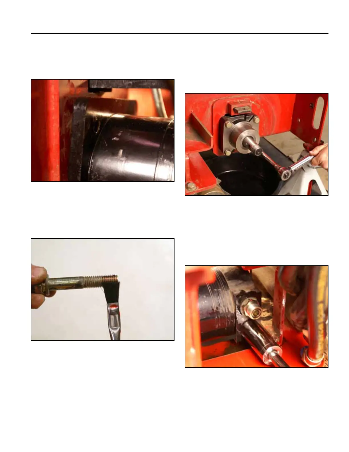
3. Position the wheel motor mounting plate on the
inside of the frame with the wide side positioned
toward the rear of the machine (Fig. 1500).
Fig 1500 PICT-4477
4. Apply a thread locking compound to the threads of
the wheel motor mounting bolts (Fig. 1501).
Fig 1501 PICT-4474a
5. Install the 4 mounting bolts and lock washers
through the wheel motor housing and frame. The top
2 mounting bolts will also thread into the mounting
plate. Torque the 4 mounting bolts to 75 ± 8 ft-lbs.
(102 ± 11 Nm) (Fig. 1502).
Fig 1502 PICT-4479
6. Remove protective caps.
7. Witha1-1/16”socket,installthehydraulicttings
into the wheel motor (Fig. 1503).
Fig 1503 PICT-4463

 Loading...


