HYDRAULIC SYSTEM
6-75TX525 Service Manual Rev. 000
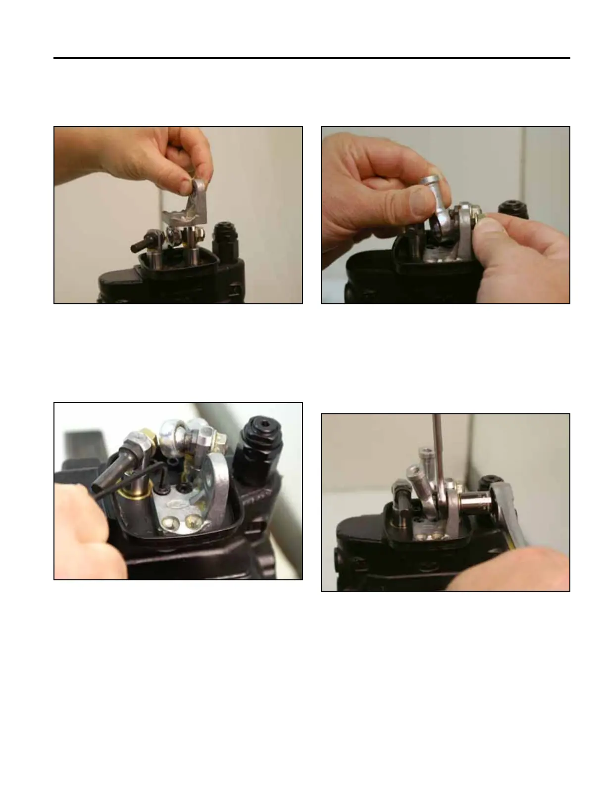
2. Position the joystick pivot on the valve assembly
(Fig. 1115).
4. Position the lift and tilt joystick joint onto the pivot
and install the nut (Fig. 1117).
Fig 1115 PICT-2598a
Fig 1117 PICT-2600a
5. Using a 13mm wrench and socket, tighten the nut
securing the joystick joint to the pivot for the lift and
tilt operation (Fig. 1118).
3. Using a 3mm Allen wrench, install the 2 hex head
screws that secure the joystick pivot (Fig. 1116).
Fig 1118 PICT-2596a
Fig 1116 PICT-2597

 Loading...


