HYDRAULIC SYSTEM
6-50 Rev. 000 TX525 Service Manual
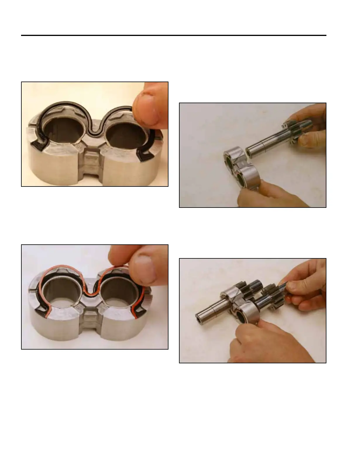
8. Install the gear seal with the lip side of the gasket
facing away from the groove of the bushing (Fig.
1018).
10. Repeat the previous 2 steps for the second bushing,
gear seal and back-up ring.
11. Making note of the markings on the bushing as-
sembly, install the drive gear into the bushing (Fig.
1020).
Fig 1018 PICT-2861
Fig 1020 PICT-2863a
12. Install the driven gear into the bushing (Fig. 1021).
9. Install the back-up ring into the bushing so that it
rests in the lip of the gear seal (Fig. 1019).
Fig 1021 PICT-2864a
Fig 1019 PICT-2862a

 Loading...


