HYDRAULIC SYSTEM
6-36 Rev. 000 TX525 Service Manual
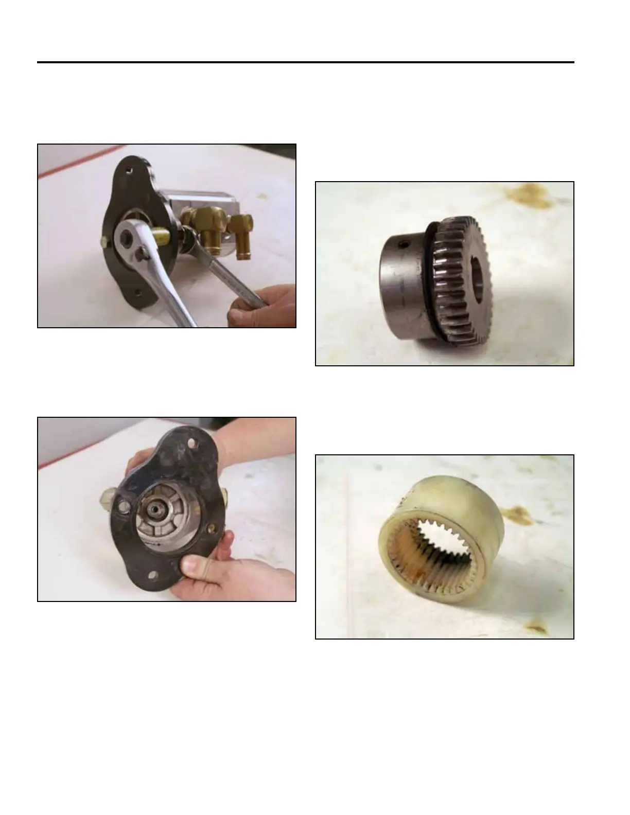
24. Using a 5/8” wrench and a 11/16” socket, remove
the 2 bolts and nuts securing the pump mount plate
to the pump (Fig. 0965).
26. Inspect the pump shaft coupler gear, the coupler
sleeve and the crankshaft coupler gear. Replace
if worn or damaged (Fig. 0967, Fig. 0968 and Fig.
0969).
Pump shaft coupler gear:
Fig 0965 PICT-4789a
Fig 0967 PICT-4796a
Coupler sleeve:
25. Remove the pump mount plate (Fig. 0966).
Fig 0968 PICT-4797a
Fig 0966 PICT-4792a

 Loading...


