HYDRAULIC SYSTEM
6-38 Rev. 000 TX525 Service Manual
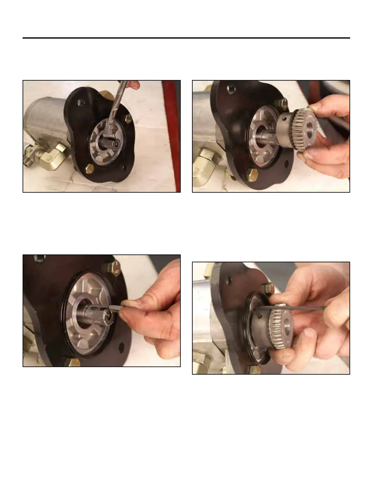
3. Apply anti-seize compound to the pump shaft (Fig.
0973).
5. Slide the coupler gear onto the pump shaft so that it
seats against the shoulder on the shaft (Fig. 0975).
Fig 0973 PICT-4806 Fig 0975 PICT-4811
6. Using a 1/8” Allen wrench, tighten the set screw
securing the coupler gear to the pump shaft (Fig.
0976).
4. Install the key into the pump shaft keyway (Fig.
0974).
Fig 0976 PICT-4814a
Fig 0974 PICT-4808

 Loading...


