HYDRAULIC SYSTEM
6-55TX525 Service Manual Rev. 000
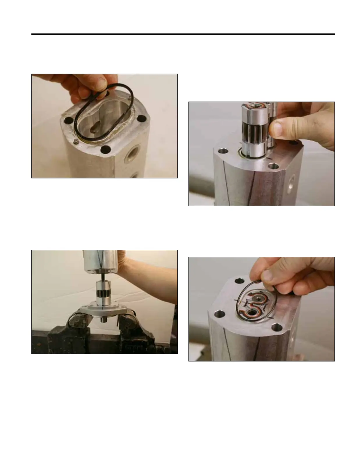
3. Install the mounting ange o-ring into the housing
groove (Fig. 1038).
5. Making note of the markings on the 6 gpm pump
assembly, slide the 6 gpm pump assembly into the
housing (Fig. 1040).
Note: The pump shaft may have to be rotated to
seat the 6 gpm pump onto the drive link.
Fig 1038 PICT-2882a
Fig 1040 PICT-2892a
6. Install the cover o-ring into the housing (Fig. 1041).
4. Making note of the markings on the housing and
mounting ange, install the pump housing over the
14 gpm pump assembly and onto the mounting
ange (Fig. 1039).
Fig 1041 PICT-2894a
Fig 1039 PICT-2890a
 Loading...


