DRIVE SYSTEM
7-13TX525 Service Manual Rev. 000
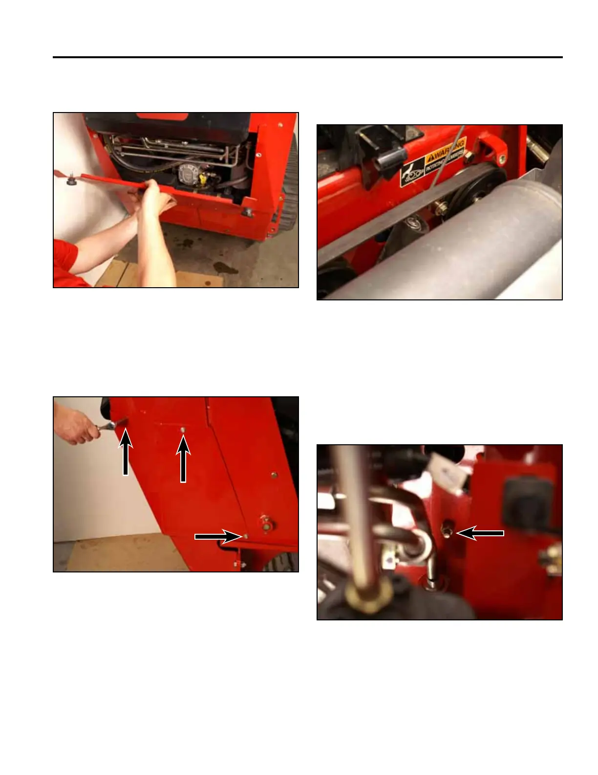
7. Remove the rear access panel (Fig. 1306). 9. Using a spring tool, remove the idler spring from its
post (Fig. 1308).
Fig 1306 PICT-4505a
Fig 1308 PICT-5360
10. Using a 1/2” socket and wrench, remove the nut
securing the idler arm assembly to the tower (Fig.
1309).
Note: The nut is located on the back side of the
tower behind the loader valve.
8. Using a 3/8” socket, remove the 3 screws securing
the right hand support panel to the tower assembly.
Remove the right hand support panel (Fig. 1307).
Fig 1309 PICT-5370
Fig 1307 PICT-4504

 Loading...


